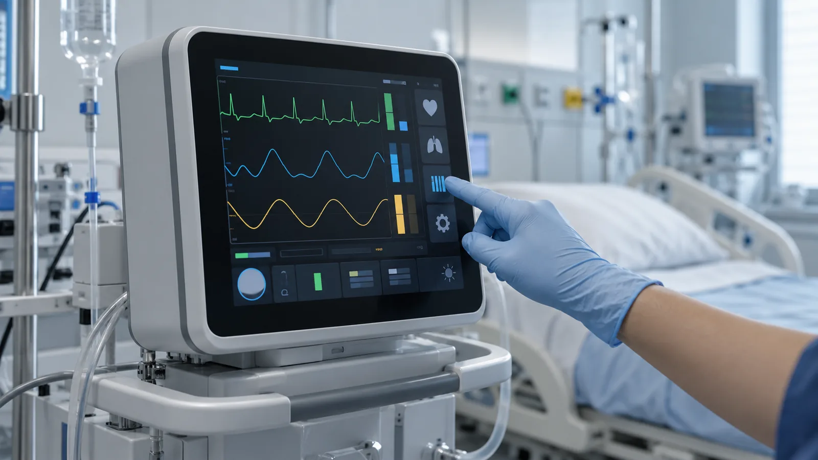
A TFT LCD module is a component inside a medical device; it is not a medical device itself. Basic safety, essential performance, electromagnetic compatibility, risk management and regulatory submission sit with the device manufacturer at system level. The display supplier's role is narrower but still important: provide accurate documentation, a controlled configuration and samples that can be validated inside the finished product.
That framing changes how selection starts. Instead of asking only “which 10.1-inch panel?”, ask who looks at the screen, from where, wearing what, under which light, how it is touched, how it is cleaned and which records the project file will need. This guide follows that order. For the general module checklist, read the seven-specification industrial TFT LCD guide; for application context, see TFTWorks medical equipment displays.
Start with the display's role in the device
“Medical equipment” covers very different screens. A bedside unit, a benchtop analyzer and a handheld diagnostic tool share almost no viewing or cleaning conditions. Write down the real use case before comparing modules.
| Equipment category | What the display must handle | Typical priorities |
|---|---|---|
| Bedside and portable monitoring | Several staff reading from different heights and angles; ward lighting that changes through the day | Viewing-angle consistency, dimming range, cleanable front |
| Therapy and infusion control panels | Dense, time-critical UI; frequent gloved touch; reading at arm's length and across a room | Touch reliability, UI contrast, accidental-touch handling |
| Laboratory and diagnostic analyzers | Long operating hours; reflections from bench lighting; occasional splashes during maintenance | Reflection control, front-stack sealing, chemical compatibility |
| Handheld and portable diagnostics | Battery limits, compact enclosure, use near windows or outdoors | Power versus brightness, small-format resolution, mechanical thickness |
Viewing angle and image consistency
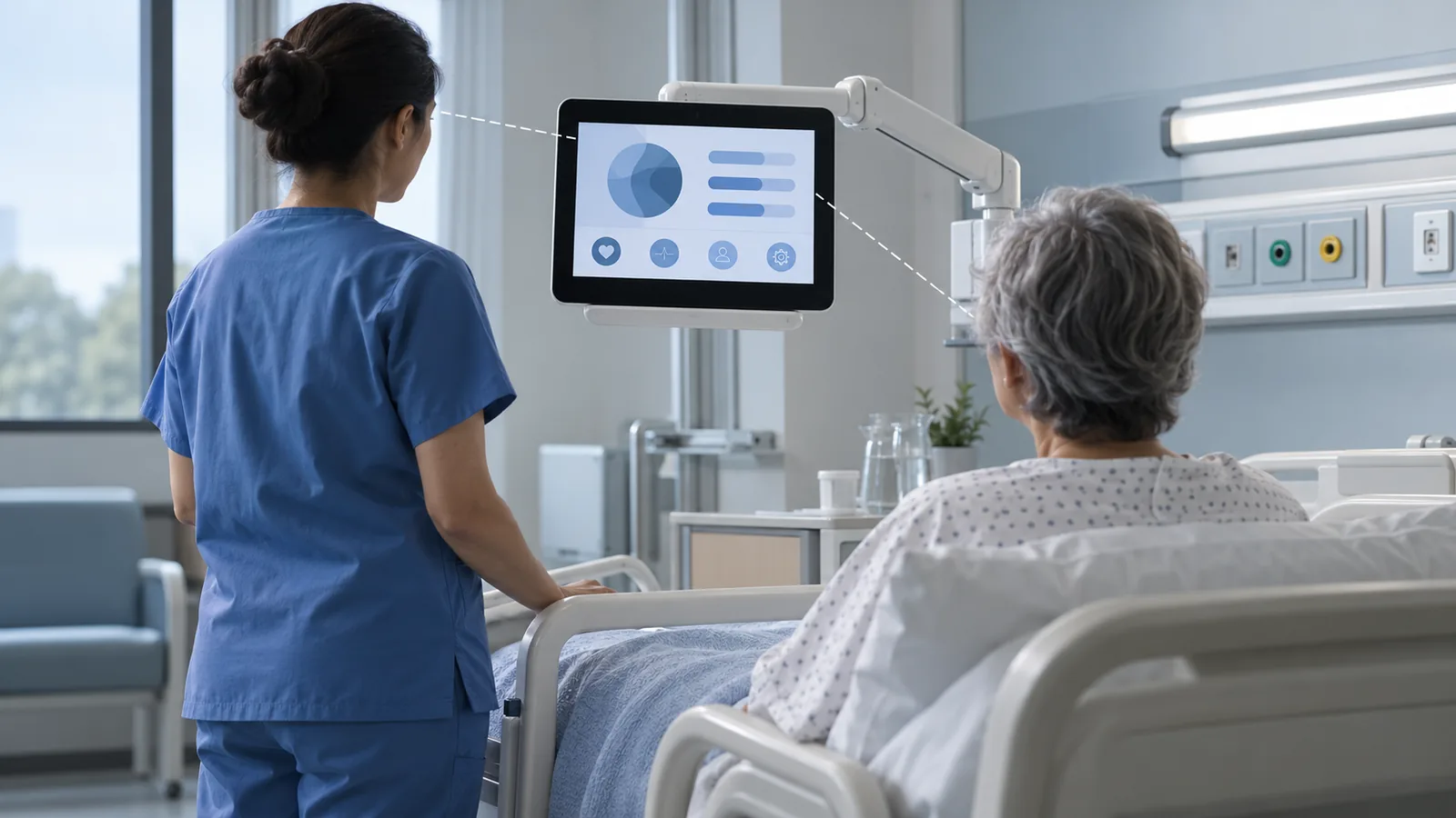
Medical screens are rarely read from one fixed point. A monitor on a bedside arm may be read by a nurse standing, a clinician seated and a technician crouched at a service panel. Panel technology decides how much contrast and color shift appear away from the normal axis. IPS panels generally hold image consistency better across wide angles, while TN panels can be a sound choice when the viewing direction is fixed and known. The trade-offs are explained in the IPS vs TN TFT LCD guide.
Brightness, reflections and dimming
Clinical lighting is not constant. A ward can be dim at night, bright at a window and lit by task lights during a procedure; portable equipment may also be used in vehicles or outdoors. Peak luminance matters, but so do three other items:
- Reflections. A bright panel can still wash out under a direct light source. Anti-glare, anti-reflective treatment and optical bonding each change reflections differently — see AG vs AR vs optical bonding and what makes a TFT LCD sunlight readable.
- Low-end dimming. In a dark room, the lowest usable brightness is as important as the highest. Confirm the dimming range and the dimming method with the actual driver and firmware.
- Heat and power. Higher luminance raises backlight power and enclosure temperature. Review the thermal trade-offs of high-brightness TFT LCDs and the 800 vs 1000 vs 1200 nit comparison before setting a target.
If cameras or recording sensors operate near the screen, also check how the backlight dimming signal behaves in the actual setup instead of assuming it is invisible to them.
Touch: gloves, moisture and accidental input
Touch behavior should be specified with the real contact conditions: thin or thick gloves, damp or contaminated fingertips, disinfectant residue and the cleaning routine itself. A touch stack that works on a clean bench can behave differently under these conditions.
- PCAP suits a flush, cleanable front and can be tuned for gloves and moisture. Glove thickness, cover-glass thickness and controller tuning must be validated together — see the industrial PCAP touchscreen design guide.
- Resistive touch responds to many objects but uses a flexible top film that affects optics and surface wear. The PCAP vs resistive comparison lists the checks.
- Accidental touch. Wiping a screen can trigger input. Plan a UI lock, a cleaning mode or a controller setting, and test it during the cleaning procedure rather than only during normal operation.
Browse industrial TFT modules with PCAP for published touch-enabled examples, then confirm the current configuration for your project.
Front stack and cleaning
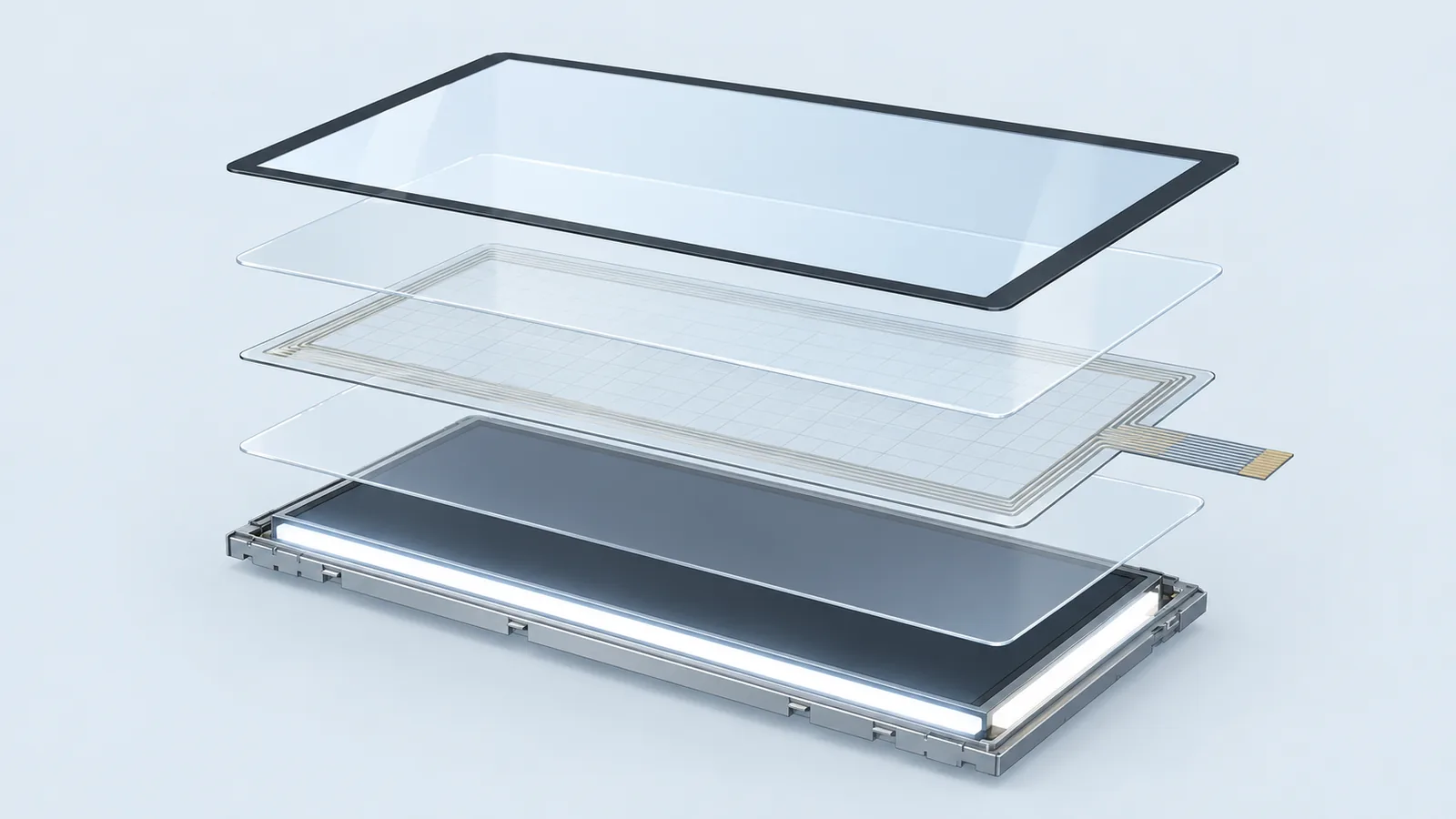
The front stack — cover glass, bezel, gasket, adhesive, touch sensor and TFT module — decides how easily the equipment can be cleaned and how long the screen stays readable. State the actual disinfectants, wipe method and cleaning frequency in the requirement, then verify the finished stack against them.
| Choice | Cleaning benefit | Watch-outs |
|---|---|---|
| Flush cover glass with PCAP | Smooth surface with few edges where residue can collect | Printed-border durability, glove and wet-touch tuning, glass edge treatment |
| Optical bonding | No internal air gap where dust or moisture can collect; fewer internal reflections | Process tolerance, rework limits, cost and lead time, thermal expansion |
| Air-gap stack with gasket | Simpler assembly and serviceability | Gasket compression, long-term seal, internal reflections |
| Resistive film front | Works with many contact objects | Surface wear, optical clarity, chemical compatibility of the film |
Do not treat the display module as the part that provides an ingress rating; sealing is a property of the complete enclosure and front-panel assembly. The washdown HMI design guide and the cover glass design guide separate those responsibilities. For bonded assemblies, see optical bonding for industrial TFT LCDs. Published bonded PCAP examples to review include DS-T035SGV-01CP (3.5-inch), DS-T050BWSA-02CP (5-inch) and DS-T101HIEWA-01CP (10.1-inch). They are starting points for a front-stack review, not a statement that any module is qualified for a specific medical device.
EMC, ESD and electrical planning
Medical electrical equipment is evaluated at system level against safety and EMC requirements; IEC 60601-1 covers basic safety and essential performance, and the EMC collateral standard in the 60601-1-2 series addresses electromagnetic disturbances. No IEC 60601 conformity claim is made here for the listed display modules. Applicable standards, editions, collateral or particular requirements and system-level evidence must be determined for the device, intended use and target market. What the display team can do is reduce risk early:
- Review the display link (RGB, LVDS or MIPI) for emission risk, cable or FPC length, shielding and grounding. See the TFT LCD interface guide and FPC customization guide.
- Check backlight-driver switching noise and how the touch controller tolerates conducted noise and ESD at the front panel.
- Run pre-compliance checks with the real enclosure, cable and power supply instead of waiting for the final test.
- If the host cannot drive the native interface, plan the conversion path with the controller-board selection guide.
Documentation, change control and lifecycle
Medical projects are paper-intensive, and a missing document can hold up an otherwise good display choice. TFTWorks is operated by Guangdong Dexing Microelectronics Co., Ltd., and the factory and quality page lists management-system documents for DISEA, including an ISO 13485:2016 document. Read its certified scope and validity dates. ISO 13485 describes requirements for a quality management system; a certificate describes the organization's management system and does not approve a particular display module for a particular medical device.
| Item | Why it matters | Confirm for the exact model |
|---|---|---|
| Current datasheet and approved drawing | They define the configuration you validate and later build | Revision number, outline, FPC, pinout, timing |
| Frozen configuration | Backlight, FPC, cover glass, adhesive and touch firmware can change results | Which parts and settings are locked for your release |
| Change notification | A silent material or process change can invalidate validation | Which changes trigger notice and how far ahead |
| Traceability | Supports investigations and field actions | Lot or date coding and how records can be retrieved |
| Declarations required by your regulatory file | Different markets and customers ask for different material or substance statements | Which declarations exist for this model and their dates |
| Availability and last-time-buy planning | Medical products often stay in service for many years | Expected supply period and how end-of-life would be communicated |
| Sample acceptance criteria | Prevents disputes about what “pass” means | Electrical, optical, mechanical and environmental checks |
Use the sample validation checklist to turn those acceptance criteria into bench and in-product tests, and the obsolete LCD replacement workflow if you are replacing a display in an existing design.
A practical selection sequence
- Define intended use and the user group. Who reads and touches the screen, and how often?
- List environmental and cleaning conditions. Lighting range, temperature, disinfectants and wipe method.
- Set viewing and brightness targets. Include the angles that matter and the dimming range.
- Choose the touch and front-stack approach. Gloves, moisture, cover glass, bonding and sealing.
- Match the interface to the host. Confirm native output, timing, FPC route and initialization.
- Plan EMC and ESD checks. Use the real enclosure and cabling.
- Agree the documents and change control. Freeze the configuration before sampling.
- Validate samples in the finished product. Compare results with the acceptance criteria agreed in steps 3 to 7.
For a broader requirements list to send with an enquiry, use the industrial TFT LCD requirements checklist.
Medical equipment TFT LCD FAQ
Does ISO 13485 make a TFT LCD module medical-grade?
No. ISO 13485 specifies requirements for a quality management system for medical-device organizations. A manufacturer's certificate shows the scope of that management system; it does not approve a specific display module for a specific medical device. The device manufacturer remains responsible for risk management, system-level safety and regulatory evidence.
Can an industrial TFT LCD be used inside a medical device?
It can be evaluated as a component, but suitability is decided by the device's intended use, risk analysis and validation — not by the module name. Define viewing, touch, cleaning, EMC and documentation requirements first, then verify them on samples inside the finished product.
Is PCAP or resistive touch better for gloved medical use?
PCAP is common for flush, cleanable front panels and can be tuned for gloves and moisture, but glove thickness, cover-glass thickness and controller tuning must be validated. Resistive touch responds to many objects but uses a flexible top film that affects optics and wear. Test with the gloves and cleaning agents your users actually use.
Does a medical front panel need optical bonding?
Not always. Optical bonding removes the internal air gap, which can reduce internal reflections and prevent dust or moisture from collecting between layers. It also adds process, cost and rework considerations. Decide using ambient light, cleaning exposure, stack tolerances and validation results.
Technical references
- ISO 13485:2016 — Medical devices — Quality management systems — Requirements for regulatory purposes: ISO's page for the standard.
- IEC 60601-1 — Medical electrical equipment, Part 1: General requirements for basic safety and essential performance: IEC webstore listing; confirm the applicable edition for the project.
- IEC 60601-1-2 — Electromagnetic disturbances: requirements and tests: official scope of the EMC collateral standard.
Send Us Your Medical Display Requirements
Share the equipment type, host interface, target size and resolution, touch and cleaning requirements, and any documents your project file needs. TFTWorks will review standard modules and customization options against the exact configuration.
Publisher and scope. Published by TFTWorks, operated by Guangdong Dexing Microelectronics Co., Ltd. This guide is general engineering information. It does not replace project-specific engineering review, risk management or regulatory advice, and it does not state that any module is approved for a particular medical device. Request the current model-specific datasheet and drawing before release.