Short answer
An industrial TFT cover glass must be specified as part of the complete front-panel assembly. Define its material, thickness, outline, printed window, edge treatment, mounting support and optical stack together. A thicker or chemically strengthened lens is not automatically the best design: the choice must also work with the touch sensor, enclosure, adhesive process and intended cleaning conditions.
This guide focuses on the controlled lens drawing and assembly review. It does not assign universal glass thicknesses, impact ratings or touch limits. Those require the selected materials, controller documentation and finished-product validation. Treat concept illustrations as explanations, not as released manufacturing drawings.

Establish the assembly boundary before drawing the lens
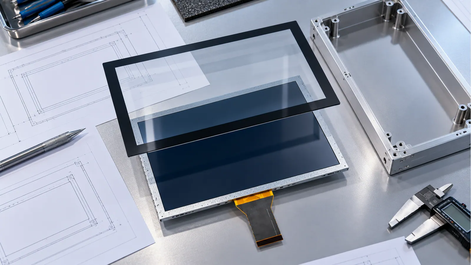
Decide what the supplier is delivering: bare LCD, LCD with touch sensor, bonded display stack, or a front-panel assembly with a custom lens. These are different quotation boundaries. A lens sized only from the LCD's metal outline can miss the sensor border, adhesive land, connector routing or enclosure support. The visible opening is also not the same as the module outline or the LCD's active area.
Assign responsibility for each interface. Identify who controls the glass drawing, printing artwork, bonding process, bezel, gasket and touch configuration. If the enclosure designer and display supplier use different reference datums, a sample that appears correct separately may not assemble reliably. Put the common datums and tolerance ownership into the drawing package before requesting tooling.
Specify installation orientation and which surface faces the user. Include cable exit direction and the relationship between the lens, sensor and LCD. Do not rely on an unannotated photograph to communicate front and rear orientation, especially when printing is on the inner surface and a transparent lens can be viewed from either side.
Write a cover-lens specification that can be inspected
Use a requirements table to separate drawing-controlled features from performance that must be tested. The following is a review template, not a prescribed specification.
| Feature | Define on the controlled package | Verify on the assembled sample |
|---|---|---|
| Glass material and thickness | Material designation, nominal thickness and tolerance | Optical appearance, touch operation and supported assembly behavior |
| Outline and corners | Dimensions, radii, datums and tolerances | Enclosure fit, edge clearance and installation access |
| Viewing window | Position, dimensions and relationship to active area | No hidden pixels, visible adhesive or unexpected border |
| Printing | Surface, artwork revision, color reference and inspection rules | Appearance, light leakage and compatibility with bonding |
| Edge treatment | Approved profile and acceptable edge condition | Handling damage, support contact and exposed-edge suitability |
| Mounting and adhesive | Support zones, attachment surfaces and keep-out areas | Flatness, retention and effect on the display and touch stack |
| Surface finish | Agreed optical or protective treatment | Reflections, image clarity, cleaning and wear behavior |
Add an agreed cosmetic inspection method. Lighting, viewing distance, display state and allowable defects should be explicit; otherwise two inspectors may judge the same sample differently. Ask the supplier to confirm which characteristics can be measured during production and which require sample-level qualification.
Choose thickness with touch and mounting constraints in view
Thickness is not a stand-alone strength guarantee. Glass material, edge quality, support conditions and loading all matter. Review the actual exposed area and whether force is carried by the enclosure, the lens attachment or the display stack. Do not ask the LCD or its bonding layer to act as an undocumented structural support.
For projected capacitive touch, cover construction is part of the sensing system. Controller vendors document different capabilities for challenging front panels, gloves and moisture. Microchip's maXTouch controller overview illustrates why those capabilities are controller-specific. It does not establish the capability of an unrelated TFTWorks assembly, nor does it provide a universal maximum lens thickness for every PCAP design.
Request a review of the proposed material, thickness, sensor layout and bonding arrangement using the actual controller and firmware. Include the intended gloves and required edge behavior. Test the thickest permitted production stack, not just a nominal sample. A lens tolerance, adhesive variation or alternative material can change the configuration that was originally tuned.
Avoid transferring capacitive-button specifications to a multi-touch display. Buttons, sliders and large PCAP matrices have different electrode geometries and sensing requirements. A vendor demonstration through a thick overlay is not evidence that a specific industrial touchscreen will provide the same behavior. The industrial PCAP design guide explains how to define the full touch-validation boundary.
Locate printing and the viewing window carefully
The printed border can hide inactive areas, adhesive and internal parts, but must not cover required pixels or interfere with the defined assembly process. Dimension the opening relative to the shared datums, allowing for the agreed positional tolerance of the LCD, sensor and lens. Review the window in both a bright display state and a dark state before approving artwork.
Specify the printing surface and drawing orientation unambiguously. Include the artwork revision, color reference, opacity requirement and any light-transmitting areas. A logo, indicator window or decorative line can look acceptable in a rendering but produce a different result over the real backlight. Evaluate the exact sample under the expected illumination.
Review inks and coatings with the bonding supplier. Establish whether printed steps, coating boundaries or intended adhesion surfaces require process changes. Keep cosmetic approval separate from adhesive compatibility; a print can pass a visual review while still needing further process validation. Use the approved material and process documentation rather than assuming that all black borders are equivalent.

Protect edges through manufacture, assembly and service
An exposed glass edge deserves its own engineering review. Specify the approved profile and inspectable edge condition rather than describing it only as “smooth.” Discuss cutouts, holes, corner transitions and the risk of contacting hard fixtures. Let the glass supplier determine the manufacturable treatment and process sequence for the chosen material.
Corning's controlled edge-damage study shows that mechanical contact can introduce strength-limiting edge damage. That supports controlling handling and edge condition; it does not assign an impact rating to a TFTWorks front panel or prove that the panel uses Corning glass.
Design installation fixtures and service access so that tools do not pry against exposed glass. Review contact points under the enclosure's tolerances, including places where a gasket, clamp or frame could create a concentrated load. A successful loose-lens inspection does not prove that the same lens remains acceptable after installation pressure is applied.
Ask how lenses are protected between printing, bonding, transport and final assembly. Define when an edge defect requires rejection and who records it. If an edge treatment or glass source changes, identify whether the original mechanical and cosmetic qualification still applies. Supplier change control should cover these features as well as overall dimensions.

Choose the optical stack without duplicating its specifications
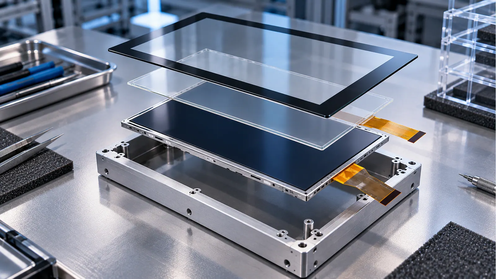
Decide whether the front construction includes an air gap or optical bonding, and identify every relevant surface. The cover, sensor, adhesive and LCD must be evaluated as an assembly. Do not specify an arbitrary adhesive thickness or chemistry from a generic image; use a process approved for the actual materials and geometry.
Surface treatments and bonding address different optical interfaces. Compare the final screen under the lighting and viewing angles the operator will encounter, not only under a diffuse studio light. Use the AG, AR and optical-bonding comparison to separate the decisions, then the optical-bonding design guide for process and stack validation.
Define cleaning agents, exposure method and expected frequency as inputs for the supplier's compatibility review. Do not turn an attractive smooth front surface into a promise of resistance to every disinfectant, solvent or industrial cleaner. Test the approved cleaning procedure on the selected coating, print, adhesive and seals. Record visible changes and functional results against the agreed criteria.
A cover-glass design release flow
- Establish the supply boundary and the owner of the lens, sensor, bonding and enclosure documents. Stop if no one owns an interface between them.
- Place the active display and required touch area within the proposed front opening. Resolve datum, alignment and tolerance questions before finalizing the printed border.
- Submit the material, thickness, edges and attachment zones for manufacturing and touch review. Resolve incompatible features before commissioning production tooling.
- Approve a complete-stack sample using the intended enclosure, firmware, viewing conditions and cleaning procedure.
- Freeze drawing, artwork, materials and process revisions. Define which substitutions or changes trigger a new sample approval.
For enclosure sealing and water exposure, continue with the washdown HMI guide. A custom cover lens alone cannot establish the protection level of the finished housing.
Complete-stack validation checklist
- Match the lens drawing, artwork, sensor, LCD and bonding revisions to the sample identification.
- Measure key outline, opening, attachment and alignment features using the agreed datums.
- Check the visible window with full-screen edge markers and representative application screens.
- Inspect printed areas for the agreed color, opacity, defects and unwanted light transmission.
- Check reflections, text clarity, off-axis viewing and dimmed operation with the final surface treatment.
- Test touch near corners and edges with the defined gloves, contamination and grounding conditions.
- Inspect edge contact, mounting pressure, flatness and cable clearance in the final enclosure.
- Run the agreed environmental and cleaning procedures, then repeat visual and functional checks.
- Evaluate the planned repair method. Record whether the lens, display stack or complete front panel is the replaceable service unit.
Make acceptance criteria specific enough to reproduce. Record sample preparation, fixtures, inspection conditions and test duration rather than stating only “glass passed.” Product-level impact, ingress or environmental claims require an applicable test program and evidence for that product configuration. This article and its illustrations do not provide certification.

Frequently asked questions
What is the best thickness for an industrial TFT cover glass?
There is no universal answer. Select it with the material, supported opening, expected loading, touch sensor and attachment process. Obtain the supplier's design review and validate the complete production stack, including tolerances.
Does chemically strengthened glass guarantee an impact rating?
No. A strengthening process is a material and manufacturing input, not a rating for the finished enclosure. Edge condition, mounting and the defined product-level test all remain relevant. Request evidence for the exact claim being made.
Should the printed window match the LCD active area exactly?
It must be designed around the actual active area and the full positional tolerance stack. An exact nominal match without alignment allowances can hide pixels or expose unintended areas. Use the approved assembly drawing and inspect a complete sample.
Can a cover-glass change be treated as cosmetic only?
Not automatically. Thickness, material, coating, print, edge treatment or bonding changes can affect the assembly. Identify the affected optical, mechanical, touch and process checks before accepting a substitution.
What documents are needed for a useful quotation?
Supply the lens outline and opening, artwork, material preferences, touch conditions, optical-stack boundary, enclosure attachment and cleaning requirements. Mark undecided items explicitly and ask the supplier to confirm manufacturability before tooling.
Continue the front-stack review
Outdoor equipment adds solar load, moisture and enclosure decisions beyond the lens drawing; the EV-charger display guide organizes those checks. When choosing between two same-size LCD assemblies, use the 10.1-inch resolution guide to compare the complete mechanical and interface specifications.
Request a front-stack review
Send the controlled lens concept and enclosure constraints through the project review form. Include a representative screen and the required touch conditions. A coordinated drawing package gives engineering and procurement a clearer basis for quotation, sampling and production approval than a generic “custom glass” request.