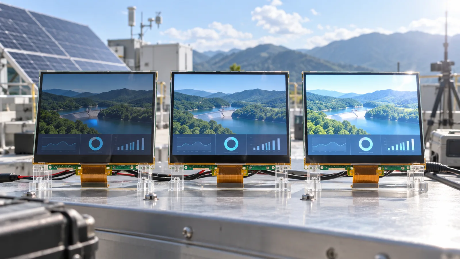
Nits and cd/m² are numerically equivalent units of luminance: 1 nit equals 1 cd/m². Luminance describes light leaving the display in a specified direction and condition. It does not directly state how much ambient light the front surface reflects or whether the black level remains readable outdoors.
For the optical principles behind reflection, bonding and surface treatment, first read What Makes a TFT LCD Sunlight Readable?. This guide focuses on choosing among approximately 800, 1000 and 1200-nit targets during project definition.
The short answer
Consider 800 nits for controlled or shaded outdoor use when reflection is low and the viewing geometry is favorable. Use 1000 nits as a stronger starting point for bright outdoor equipment, provided the full front stack preserves contrast. Consider 1200 nits when the project needs more luminance headroom and can support the added backlight, power and thermal work. These are planning ranges, not universal pass/fail thresholds.
800 vs 1000 vs 1200 nits at a glance
| Target | Where it may fit | What to verify |
|---|---|---|
| Approximately 800 nits | Sheltered kiosks, vehicle cabins, shaded panels or bright indoor equipment with controlled reflections. | Direct-sun exposure, front-surface reflectance, cover-lens transmission and worst-case viewing angle. |
| Approximately 1000 nits | A practical high-brightness starting point for many outdoor and semi-outdoor designs. | Ambient contrast in the final stack, thermal rise, power, dimming range and minimum luminance. |
| Approximately 1200 nits | Projects needing additional luminance margin in severe ambient conditions. | Whether extra output produces a meaningful contrast gain after reflection, plus LED current, heat and lifetime constraints. |
An optically well-controlled 800-nit assembly can outperform a more reflective 1200-nit assembly. Conversely, optical bonding cannot compensate for a backlight that is fundamentally too dim for the application. Select luminance and the front stack together.
Outdoor readability is an ambient-contrast problem
Ambient light raises the apparent black level because some incident light returns toward the viewer. The usable white-to-black difference therefore depends on emitted display luminance plus reflected ambient luminance. A simplified engineering view is:
When reflected ambient light is large, increasing the backlight can improve the numerator, but reducing reflection often improves both dark-state appearance and overall contrast. Measure with the final viewing angle because specular glare can be strongly directional.
Account for every layer in front of the TFT
- Touch panel: sensor layers, electrodes and adhesives affect transmission, haze and reflection.
- Air gap: additional refractive-index boundaries can create visible reflections.
- Optical bonding: filling the gap can reduce internal reflections and improve light transmission when the process and materials are appropriate. Review the bonding benefits, limits and design inputs.
- Cover lens: glass or plastic material, thickness, printing and surface treatment affect transmission and glare.
- AG treatment: diffuses mirror-like reflections but can add haze or sparkle; evaluate text and fine graphics.
- AR treatment: can reduce surface reflection but requires durability, cleaning and angle/color evaluation. Compare AG, AR and optical bonding before freezing the front stack.
- Polarizers and films: orientation, temperature and UV exposure can affect optical performance.
Do not multiply optimistic supplier transmission values and call the result a finished-display specification. Measure an approved assembly using a defined method. If PCAP or resistive touch is still undecided, use the industrial touchscreen comparison before freezing the optical stack.
Compare like-for-like luminance specifications
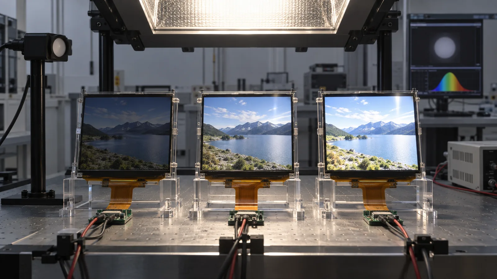
Ask whether the published number is typical or guaranteed minimum. Confirm center-only or multi-point measurement, uniformity definition, color temperature, warm-up time, backlight current and ambient temperature. A “1000-nit” typical module may not guarantee 1000 cd/m² at every point, unit, temperature or lifetime condition.
Camera photographs are useful for documenting glare geometry and visible artifacts, but automatic exposure and tone mapping make them unreliable for comparing absolute luminance. Use a calibrated luminance meter, spectroradiometer or imaging photometer with controlled geometry when the decision is quantitative.
Higher luminance changes power and thermal design
Increasing backlight output may require more LED electrical power, depending on the LED system and optical efficiency. The resulting heat affects the LEDs, light guide, polarizers, liquid crystal, touch electronics and sealed enclosure. Solar loading can raise internal temperature even when ambient air is within specification.
Review maximum current, LED string voltage, driver efficiency, PCB temperature, enclosure heat path and derating. Ask for backlight lifetime conditions rather than assuming the same life at every drive level and temperature. Use automatic or commanded dimming if the unit does not need maximum brightness continuously, but validate the minimum usable duty cycle and PWM behavior. The dedicated guides explain how to build a high-brightness TFT thermal plan and verify a quoted backlight lifetime.
Select by the real outdoor scenario
| Scenario variable | Why it matters |
|---|---|
| Direct sun, open sky or permanent shade | Changes both incident illumination and glare geometry. |
| Viewing direction and operator position | Avoiding specular reflection can be as important as increasing luminance. |
| Dark UI or bright UI | Content luminance and local contrast affect legibility. |
| Protective window and touch stack | Each layer changes transmission, reflection and haze. |
| Sealed enclosure and solar load | May limit sustainable backlight power at high ambient temperature. |
| Night operation | Requires a wide, stable dimming range without flicker or washed-out blacks. |
| Gloves, rain and contamination | Influences touch selection, surface treatment, cleaning and real reflected light. |
How current TFTWorks products fit the comparison
The current public catalog includes verified examples near the comparison ranges: the DS-T104QXHA-03 10.4-inch module at 850 cd/m² typical, the DS-T080BXEA-05 8-inch module at 950 cd/m², and multiple 1000 cd/m² options such as DS-T070BAHA-02 7-inch 1024×600 and DS-T101HIEWA-01 10.1-inch 1280×800.
These links support an initial shortlist only. Confirm the current datasheet, minimum/typical definition, touch/bonding configuration, operating temperature, interface and mechanical drawing. A 1200-nit target is not represented by a verified standard product on this page; send it as a project requirement for feasibility review instead of assuming availability.
Browse the high-brightness TFT catalog and sunlight-readable selection page for additional project paths.
A practical luminance-selection workflow
- Define the worst viewing condition: illumination, sun direction, operator position, viewing distance and required content.
- Freeze the touch, cover lens, air gap or optical bonding, and surface-treatment concept.
- Set the required measurement plane and whether luminance is minimum or typical.
- Shortlist 800, 1000 or 1200-nit-class solutions using power, thermal and optical constraints.
- Build production-intent samples with the actual front stack, enclosure and backlight driver.
- Measure luminance, uniformity, reflected light and ambient contrast at required angles and temperatures.
- Run readability tasks using representative text, icons, warnings, maps and video—not only a white screen.
- Validate dimming, cold/warm startup, solar heating, power, EMC and backlight life assumptions before release.
Outdoor validation plan
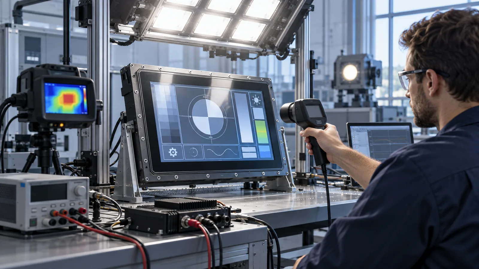
Test both controlled laboratory illumination and the real installation geometry. Use the finished cover lens, bezel, seal, touch sensor and bonding condition. Record ambient illumination, display drive, measurement angle, distance and temperature so results can be repeated.
Check white and dark content, small text, fine lines, color-coded alarms and off-axis viewing. Inspect glare, haze, sparkle, moiré, touch visibility and polarizer behavior with required eyewear. Run maximum backlight long enough to reach thermal equilibrium, then repeat at reduced brightness and night settings.
Common brightness-selection mistakes
- Treating “sunlight readable” as a standardized pass/fail label.
- Comparing bare-panel luminance with finished-system luminance.
- Choosing 1200 nits without measuring reflection or checking thermal margin.
- Approving a display from photographs with different camera exposure.
- Ignoring minimum luminance, uniformity, temperature and lifetime conditions.
- Testing only a white screen instead of the real UI and viewing task.
What to send for an outdoor TFT review
- Target size, resolution, interface, touch and mechanical envelope.
- Outdoor condition: direct sun, shade, orientation, season and viewing position.
- Required 800, 1000 or 1200-nit target and whether it applies before or after the front stack.
- Cover-lens material, thickness, printing, AG/AR treatment and bonding requirement.
- Operating/storage temperature, enclosure sealing and solar-load assumptions.
- Available power, backlight driver, dimming range and duty cycle.
- Required measurement and visual acceptance method.
Send these requirements for an optical and module-fit review. Unknown fields can be marked as unknown so they become explicit validation items.
Technical references
- EIZO — About Optical Bonding: air-gap reflection, transmission, visibility and condensation considerations.
- 3M — Anti-Glare Filter Technical Data: how an AG surface diffuses mirror-like reflections and the tradeoff data to review.
- 3M — Industrial Display Enhancement: optical films, brightness efficiency, reflection control and solar-load context.
- Radiant Vision Systems — Display Readability Under Ambient Light: controlled illumination, luminance and contrast measurement context.