Short Answer
Split the requirement three ways. The front panel and cover lens own the sealing plane, the cleanability of the joint and the chemical resistance of the visible surface — this is where the IP code is earned. The enclosure owns pressure equalisation, drainage, material compatibility and the thermal path, which is where "passed the spray test but has water inside" comes from. The display module owns the temperature range across the cleaning transient, the optical stack, the behaviour of the touch layer when wet, and whether an internal air gap exists for condensation to form in. Ask a module supplier for an IP rating and you will get either a wrong answer or a careful one.
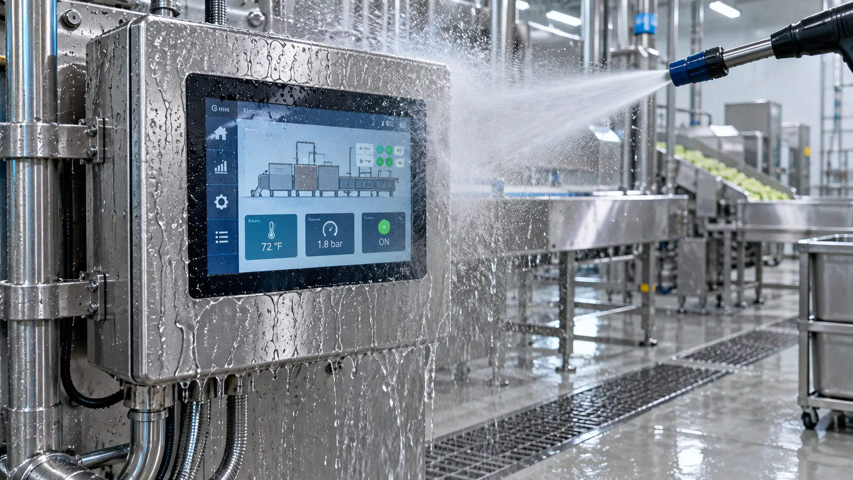
What an IP Code Actually Describes
The IP code in IEC 60529 rates an enclosure: the first digit for solid objects and dust, the second for water. The tests are specific procedures, not general statements of toughness.
| Code | Test condition in outline | Typical washdown relevance |
|---|---|---|
| IPx5 | 6.3 mm nozzle, about 12.5 L/min, from roughly 3 m, several minutes from all practicable directions | Routine hose-down cleaning; a common minimum for a food-adjacent panel |
| IPx6 | 12.5 mm nozzle, about 100 L/min, from roughly 3 m — powerful jets | Heavier cleaning regimes and exterior equipment |
| IPx7 | Immersion to 1 m for 30 minutes | Flooding or submersion risk, not cleaning pressure |
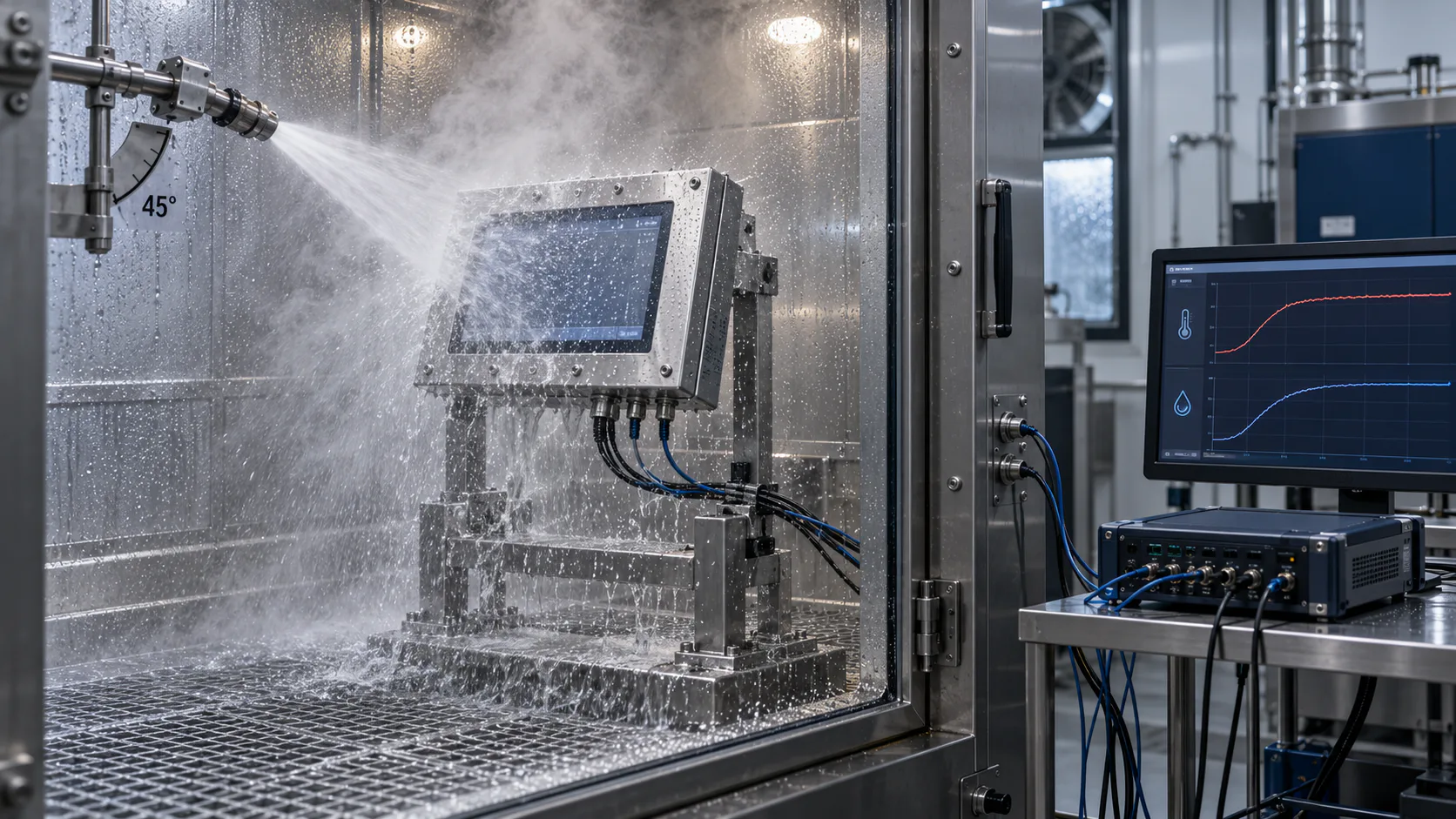
| IPx9 / IP69K | High-pressure, high-temperature jets — water near 80 °C at roughly 80 to 100 bar, close range, from several defined angles (ISO 20653, originally DIN 40050-9) | Hygienic food, beverage, pharmaceutical and vehicle-wash environments |
Two consequences matter for a display design. First, these digits are not a ladder you climb: passing the high-pressure hot-jet test does not demonstrate immersion resistance, which is exactly why hygienic equipment is marked IP66/IP69K or IP67/IP69K with two separate test results behind it. Second, none of these tests can be applied to a TFT module. A display module is an open assembly — a backlight cavity, a metal frame with gaps, and a flexible circuit tail leaving the body. There is no enclosure boundary to pressurise.
The Three Layers, and What Each One Owns
The useful exercise at kick-off is to write this table for your own product and assign an owner to every row. Most washdown failures trace back to a row nobody owned.
| Requirement | Display module | Front panel & cover lens | Enclosure |
|---|---|---|---|
| Ingress protection rating | None — cannot be rated alone | Owns the sealing plane and the gasket compression | Owns every other joint, gland and fastener |
| Cleaning chemical resistance | Not exposed if the panel seals correctly | Lens material, coating, printed ink, gasket | Shell material, welds, surface finish |
| Cleaning temperature transient | Operating and storage range must cover it | Conducts the heat pulse inward | Sets the thermal mass and the recovery rate |
| Condensation | An internal air gap in the optical stack is a place for it to appear | Bonded or gasketed lens decides whether that gap exists | Pressure equalisation, venting and internal volume |
| Touch behaviour when wet | Sensor and controller capability | Cover thickness and material change the tuning | Grounding path for the sensor and the user |
| Readability with a wet surface | Luminance and contrast | Surface treatment, bonding, reflection | Mounting angle and whether water sheets or beads |
| Hygienic geometry | Not applicable | Flush joint, radius, no residue trap | Drainage, sloped surfaces, fastener style |
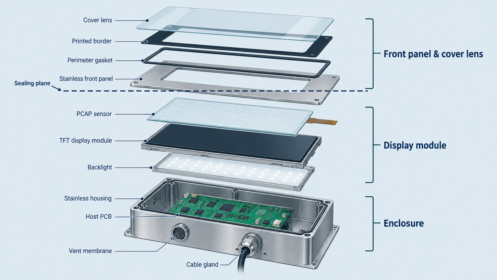
Where the Sealing Plane Goes
There are two common architectures, and the choice drives the rest of the mechanical design.
Lens-to-panel gasket
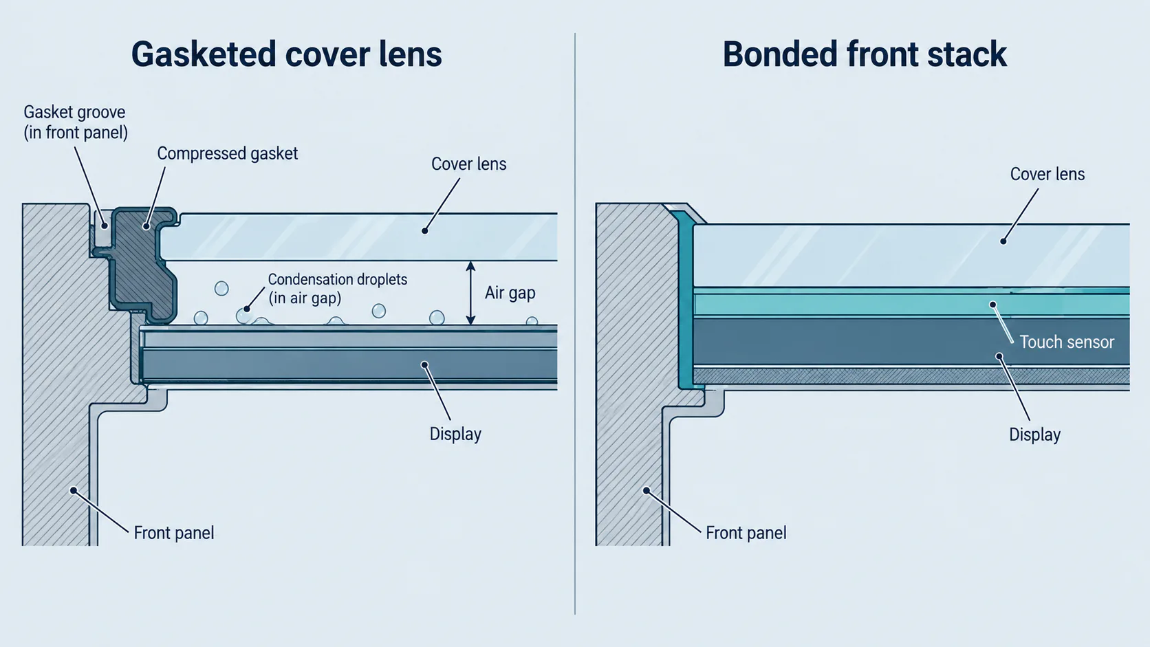
The cover lens is sealed to the front panel with a compressed gasket or a bead of adhesive, and the display sits behind it with an air gap. This is simple, tolerant of rework and cheap to service. Its weaknesses in washdown are that the gasket groove is a place residue collects unless the joint is designed flush, and that the air gap behind the lens is a volume where condensation becomes visible to the user.
Bonded lens as the front surface
The cover lens, touch sensor and display are bonded into one stack, and the lens itself becomes the sealing face against the panel. This gives a flush, wipeable front with no internal air gap, so condensation between lens and display cannot occur, and contrast in bright light improves for the reasons covered in the optical bonding guide. The trade-offs are rework cost — a damaged lens now means replacing the display assembly — and tighter stack tolerance.
In either case, one rule holds: the flexible circuit tails from the display and the touch sensor must cross the sealing plane at a controlled, sealed point. A tail exiting through the same aperture as the gasket joint is the leak that gets found in the field rather than in the lab.
The Failure That Looks Like a Leak and Isn't
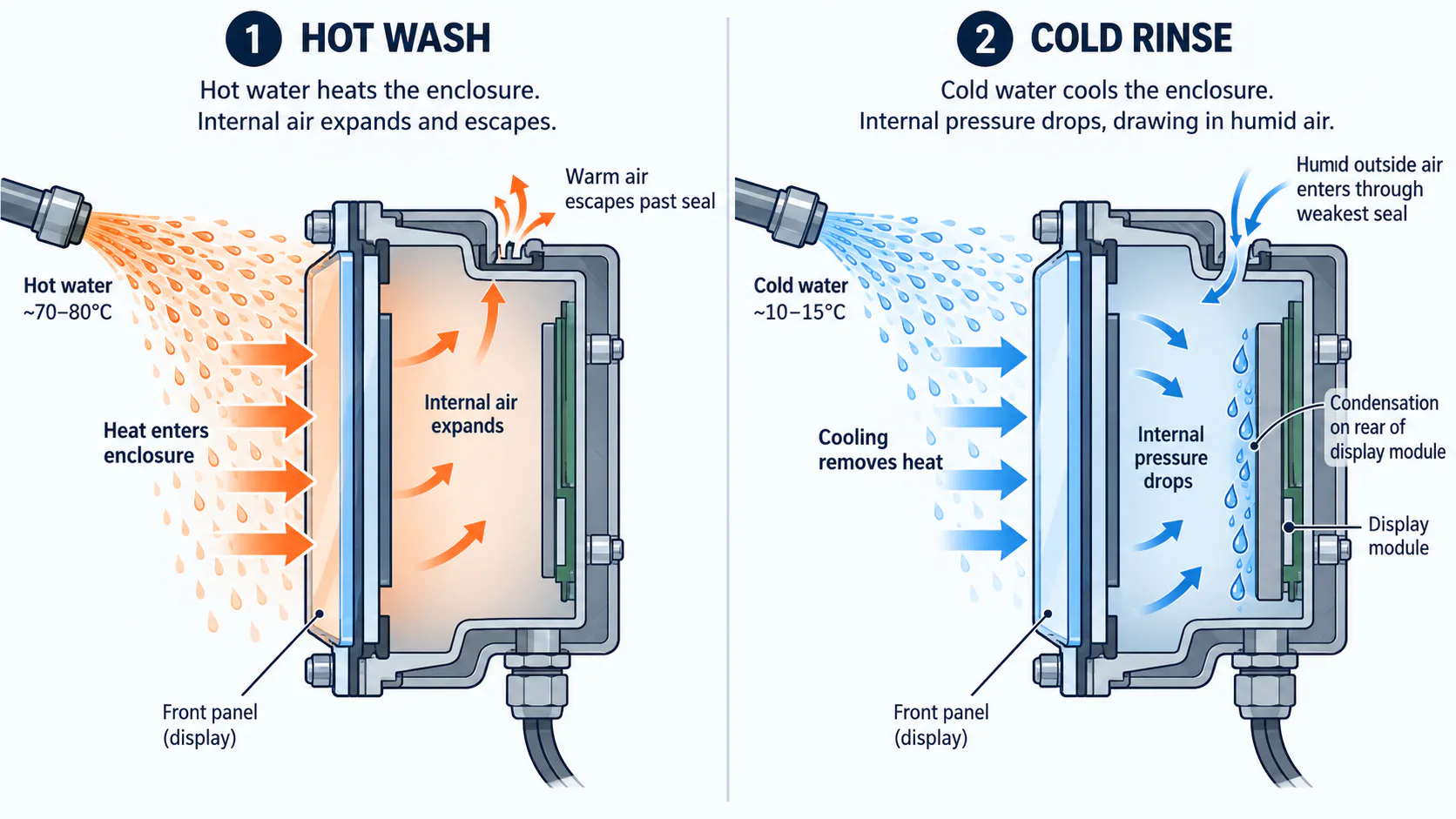
An enclosure that passed its spray test can still end up with water inside, and the mechanism is pressure rather than pressure-washing. Hot cleaning water heats the enclosure; the air inside expands and some escapes past the seals. The rinse and the surrounding air then cool it, the internal pressure drops below ambient, and humid air is drawn back in through whichever seal is weakest. Repeat that twice a shift and the enclosure accumulates moisture that no ingress test would ever have shown.
That moisture then condenses on the coldest surface. In an HMI with a bonded front and a metal rear, the coldest surface after a hot wash is frequently the back of the display or the host board. The countermeasures are a vented membrane sized for the enclosure volume, minimising the free air volume, avoiding a cold trap behind the display, and — where the duty cycle allows — keeping the electronics powered so the internal temperature stays above the dew point. A higher IP code, on its own, makes this problem worse rather than better, because a perfectly sealed enclosure with no venting cycles harder.
Chemistry, Not Just Water
Washdown is rarely water alone. Caustic foam, acid descaler, chlorinated sanitiser, quaternary ammonium compounds, peracetic acid and 70 % isopropyl alcohol all appear in cleaning procedures, often on a rotating schedule to prevent biofilm. Each attacks something different, and the display's contribution to the problem is small — the exposed materials are the lens, its coating, the printed ink, the gasket and the shell.
- Polycarbonate and acrylic lenses are vulnerable to solvent crazing and to some alkaline cleaners, particularly under mechanical stress at a mounting point. Chemically strengthened glass is far more tolerant, which is one reason hygienic panels trend to glass.
- Anti-glare etches and AR coatings have their own chemical limits. An AG surface also holds a water film differently than a smooth one, which changes both cleanability and how the screen looks while wet.
- Printed ink borders can lift at the edge under repeated hot alkaline exposure. Print position, ink system and whether the print is on the inner face are the design levers.
- Gasket material is the classic miss. Silicone, EPDM, nitrile and fluoroelastomers have very different profiles against hot caustic, chlorine and oils, and the wrong choice swells, hardens or takes a compression set — after which the panel leaks without anything looking broken.
Ask the end customer for the actual cleaning procedure — chemical names, concentration, temperature, contact time and frequency — and check materials against that list rather than against "washdown".
Touch and Readability During Cleaning
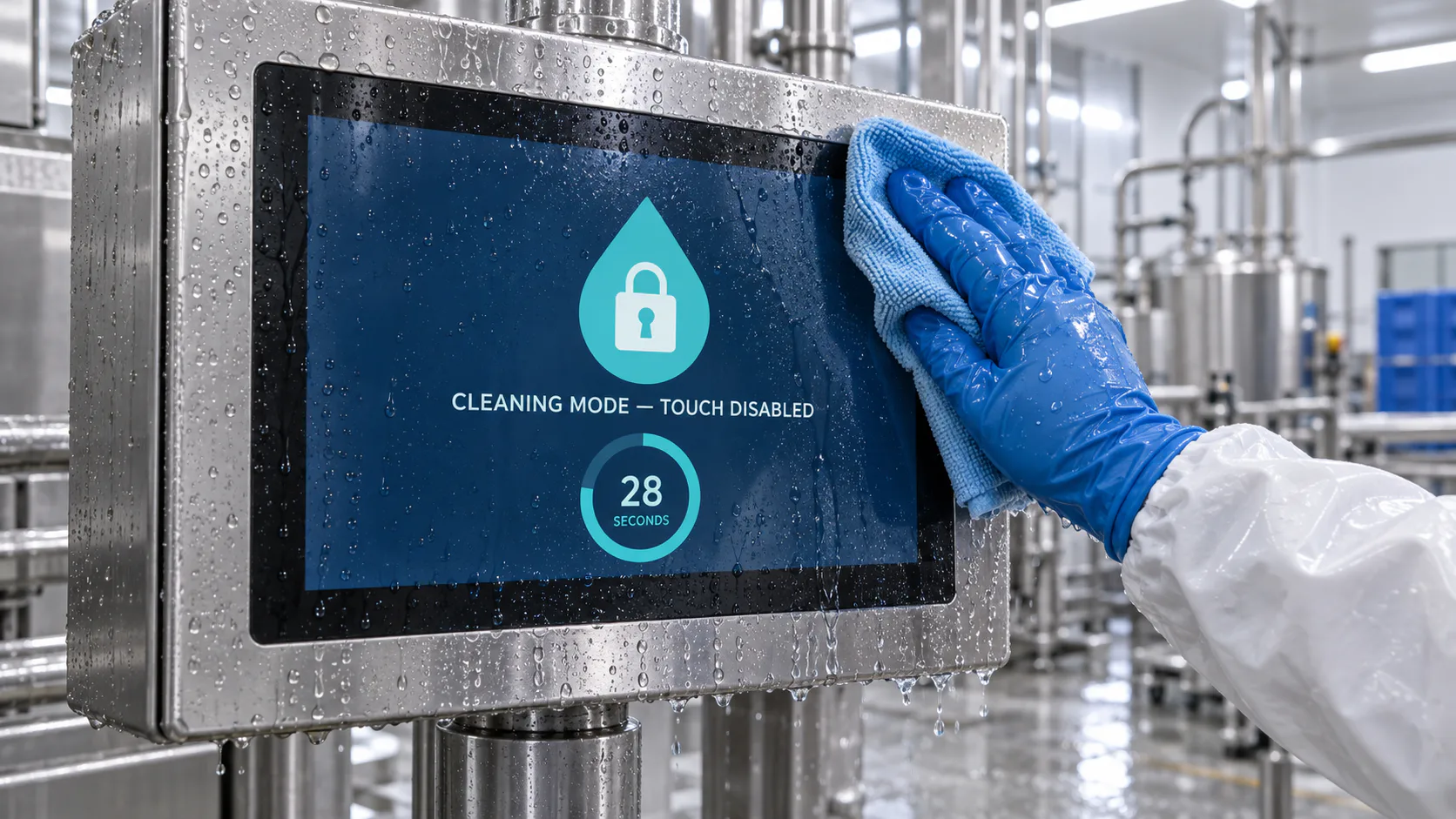
If the screen is live while it is being cleaned, water and a gloved hand will generate input. Rejection algorithms help, but the robust answer is a deliberate cleaning mode: a timed lockout the operator invokes, or an automatic lockout when the controller detects a large-area wet condition, with a clear visual state so nobody believes the machine is frozen. The sensitivity and rejection trade-offs behind that behaviour are covered in the industrial PCAP design guide, and they change with the cover lens you chose above.
Readability deserves the same attention. A wet screen scatters light, and a beaded water film on a hydrophobic surface scatters more than a sheeting film. Mounting angle matters here as much as brightness: a panel tilted to shed water dries faster and reads better than a vertical one that holds droplets along the bottom edge.
A Design Sequence
- Get the cleaning procedure in writing — chemicals, concentration, temperature, pressure, distance, frequency, and whether the equipment is powered during cleaning.
- Choose the target codes and their tests, remembering that IP69K and immersion are separate claims needing separate evidence.
- Place the sealing plane at the front panel and decide between a gasketed lens and a bonded front stack.
- Design the joint to be cleanable: flush, radiused, no upward-facing trap, fastener style suited to the hygiene standard the customer works to.
- Select materials against the chemical list — lens, coating, ink, gasket, shell — not against a generic washdown label.
- Solve the breathing problem: vent membrane, internal volume, and where the coldest surface will be after a hot wash.
- Check the display's temperature range against the transient, not against room ambient, and confirm the storage range too.
- Define the touch behaviour during cleaning, including the lockout and how the operator exits it.
- Decide the mounting angle for drainage and for readability with a wet surface.
Validation Checklist
- Ingress test to the declared codes, on production-representative units with the real gaskets at the real compression, and after the fasteners have been through their specified torque cycle.
- Cleaning-cycle endurance. Repeat the customer's real cycle — hot chemical, rinse, cool — for the number of cycles a year of service implies, then re-test ingress. A single pass proves nothing about gasket compression set.
- Chemical soak and wipe. Lens, coating, ink and gasket coupons exposed to each chemical at working concentration and temperature; inspect for crazing, haze, ink lift, swelling and hardness change.
- Condensation check. Instrument the interior with temperature and humidity logging through hot-wash and cold-rinse cycles, and inspect behind the display for moisture.
- Live touch during cleaning. Log false inputs across the full cleaning cycle with the screen unlocked, then verify the lockout and its exit path.
- Readability while wet at the real mounting angle, in the site's actual lighting.
- Thermal transient on the module. Log the display surface temperature during a hot wash and compare it to the module's operating and storage limits.
- Post-test teardown. Open a tested unit and look for water tracks, corrosion at the tails, and gasket deformation — the evidence that a pass was marginal.
What to Ask of the Display Module
With the ingress question assigned where it belongs, the display specification becomes short and answerable: an operating and storage range that covers the cleaning transient; a bonded stack if you want no internal air gap for condensation; enough luminance and the right surface treatment for a wet screen at the mounting angle; and a touch controller whose behaviour under water you can actually test. Our optically bonded PCAP modules are a reasonable starting point on the first three, with the usual caveat that the numbers below describe the module and say nothing about your enclosure.
| Model | Size / resolution | Luminance | Bonding | Operating | Storage |
|---|---|---|---|---|---|
| DS-T050BWSA-02CP | 5.0″ 800×480 IPS | 900 cd/m² | Optical bonding | −20 to 70 °C | −30 to 80 °C |
| DS-T101HIEWA-01CP | 10.1″ 1280×800 IPS | 850 cd/m² | Optical bonding | −30 to 85 °C | −30 to 85 °C |
| DS-T101BFHA-01CP | 10.1″ 1920×1200 IPS | 1000 cd/m² | Optical bonding | −20 to 70 °C | −30 to 80 °C |
On the claims in this article. Test-condition summaries for IP codes are outlines of the published standards and are not a substitute for IEC 60529 and ISO 20653. No IP rating, hygienic certification or chemical-resistance approval is claimed for any TFTWorks product; ingress and hygiene ratings belong to the finished equipment and must be established by test on that equipment. Module figures are taken from our published data and must be confirmed against the current datasheet for the exact part.
FAQ: Washdown HMI Design
Can a TFT LCD module be IP65 or IP69K on its own?
No. An IP code applies to an enclosure. A bare module is an open assembly with a flexible tail, a backlight cavity and an unsealed frame — there is no boundary to test. The rating belongs to the finished equipment, where the front panel and cover lens form the sealing plane.
Does IP69K include IP67?
Not automatically. The water digits are not a simple ladder, because the failure mechanisms of a high-pressure hot jet and of static immersion differ. Equipment needing both is marked with two codes, such as IP66/IP69K or IP67/IP69K, each with its own test evidence.
Why is there water inside an enclosure that passed the spray test?
Pressure cycling, usually. Hot cleaning followed by cooling lowers the internal pressure and draws humid air through the weakest seal, and it condenses on the coldest surface — often the back of the display. A vent membrane, a smaller internal volume and attention to cold surfaces address it; a higher IP code alone can make it worse.
Gasketed lens or bonded front stack?
A gasketed lens is cheaper and easier to service but leaves an air gap where condensation becomes visible, and the gasket groove needs a cleanable geometry. A bonded stack gives a flush, wipeable face with no internal gap and better contrast, at higher rework cost and tighter tolerance. Either way, the sealing plane is at the front panel and the tails must cross it at a controlled point.
What temperature range should a washdown display have?
Whatever covers the cleaning transient, not the room. Hot detergent or steam raises the front surface fast while the interior lags, then a cold rinse reverses it. Specify the peak surface temperature and the rate of change, check both operating and storage ranges against it, and state whether the unit is powered during cleaning.
For the surrounding application context see the industrial HMI, factory automation and medical equipment notes, or send the cleaning procedure and your panel drawing for an engineering review.