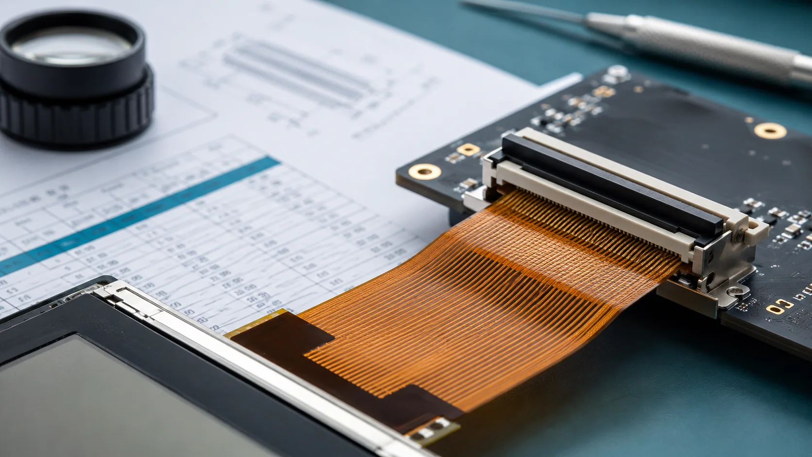
FPC customization is most useful when a standard TFT panel meets the optical and environmental requirements but the host connector, tail direction or pin definition does not fit the product. The flex is part of three interfaces at once: it connects the module mechanically, carries power and signals electrically, and influences EMC through conductor geometry and return paths.
1. Connector direction and mating geometry
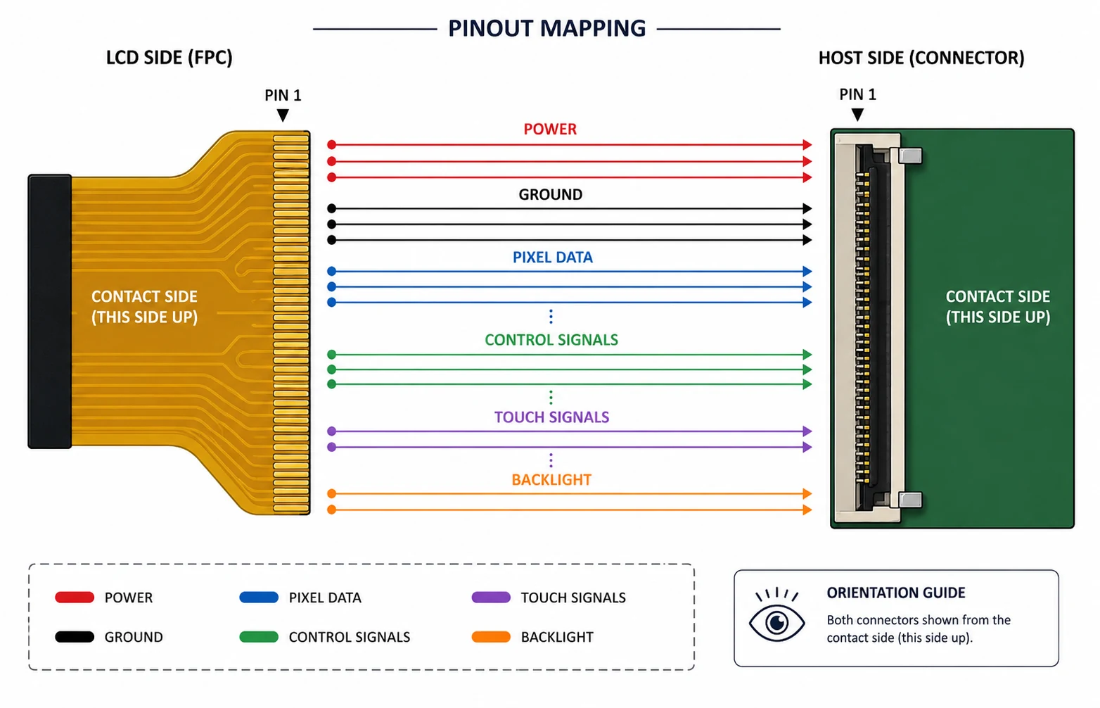
Begin with the exact host connector part number. Record pitch, circuit count, contact side, top/bottom contact, insertion direction, latch type, rated FPC thickness and recommended exposed-contact length. On the flex drawing, define pin 1 at both ends and show the viewing direction. Many expensive mistakes are simple mirror errors.
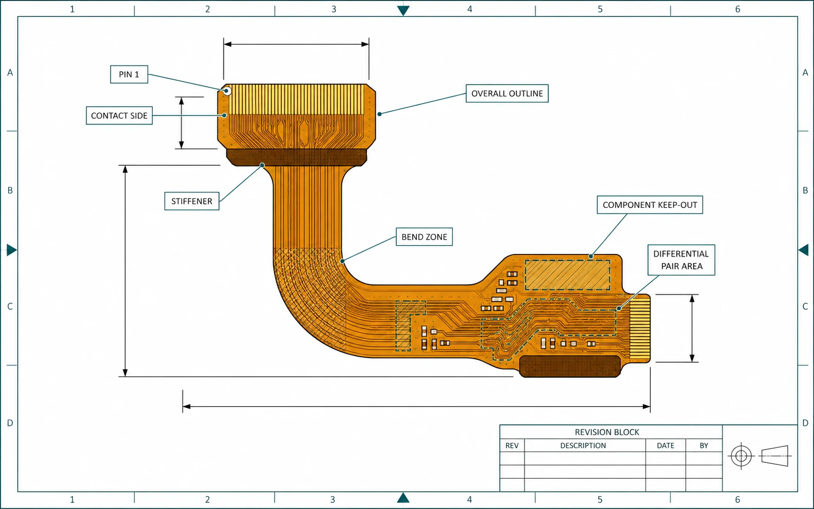
Confirm tail length from a physical datum, not from an image. Include the stiffener length and material, bare contact plating, allowable bend zone, minimum bend radius and the space needed to operate the connector latch. If the flex folds, show the fold line and whether the routing is evaluated in the assembled orientation.
2. Pin definition and signal grouping
Create a pin-by-pin cross-reference with columns for LCD pin, signal name, host connector pin, voltage domain, direction, default state and notes. Group signals by function:
- LCD logic and analog power rails
- Ground and shield/return connections
- RGB data, LVDS pairs, MIPI lanes or MCU data/control
- Pixel clock, sync, data enable and reset
- Serial configuration or touch-controller lines
- Backlight LED anode/cathode, enable and dimming
- Test, no-connect and reserved pins
Never repurpose a reserved pin without written confirmation. Avoid ambiguous names such as VCC when the design has multiple rails. Use the names and limits from the current module datasheet.
3. Power rails and sequencing
Confirm the voltage, tolerance and expected current for every rail. Document whether the host drives display signals before the LCD rail is stable, how reset is asserted and released, and how the module enters or exits sleep. Check whether inputs are allowed when the module is unpowered. Define power-off sequencing as carefully as power-on.
The backlight is a separate power path. Specify LED string arrangement, forward voltage, operating current, driver topology, enable logic and PWM dimming. Do not route high backlight current through narrow flex conductors or share a weak return path with sensitive logic without analysis. Check connector current rating and temperature rise.
4. Interface timing and signal integrity
A pin-compatible flex still needs a timing-compatible system. Use the TFT LCD interface guide to identify the required clock, synchronization, data mapping or command sequence. Then review the flex as a transmission path.
For parallel RGB, consider clock-to-data skew, simultaneous switching and a continuous ground reference. For LVDS, maintain differential pair geometry, pair matching, polarity and spacing from noise sources. For MIPI DSI, follow the panel, connector and PHY requirements for impedance, lane matching and transitions. Avoid stubs and unnecessary vias or layer changes where possible.
The correct impedance and tolerances depend on the stack-up, copper geometry, materials and interface. Put these requirements on the fabrication drawing rather than leaving them as an informal email note.
5. EMC, ESD and grounding
The FPC can carry fast edges next to the backlight, touch sensor and cover glass. Provide ground conductors or reference planes where required, and decide where shield or frame connections terminate. Keep switching backlight nodes away from touch and high-impedance control lines. Review connector shell, metal frame and chassis strategy with the complete product ground architecture.
For PCAP, display and backlight noise can reduce touch signal-to-noise ratio. The final evaluation should include the real charger, motor, radios, power supply and worst-case backlight setting—not a quiet bench supply only.
6. Mechanical durability and assembly
Define copper-to-edge clearance, stiffener, coverlay openings, bend radius, dynamic versus one-time flexing, adhesive zones and component height. Prevent the flex from rubbing on sharp chassis edges. Ensure the connector latch is accessible and that assembly does not pull the LCD bond area.
If components are mounted on the flex, include keep-outs, height limits, protective materials and thermal considerations. Mark all critical dimensions and tolerances from stable datums. A photo can clarify orientation, but the approved drawing must control production.
7. What the controlled FPC drawing should contain
Outline, thickness, connector pads, pin 1, stiffeners, bend/fold zones, component and adhesive keep-outs.
Copper, base film, coverlay, stiffener and contact-finish requirements.
Net names, voltage/current limits, differential pairs, impedance/matching requirements and test points.
Critical dimensions, conductor/space constraints, pad alignment and overall tail position.
Part number, revision, date, orientation view and traceable change history.
Continuity/short test, dimensional inspection and any interface-specific checks.
8. Sample confirmation before release
- Drawing review: mechanical, hardware, firmware and supplier sign the same revision.
- Continuity check: verify every pin mapping and check shorts before connecting the module.
- Current-limited bring-up: power rails and backlight are observed before full operation.
- Signal verification: inspect clocks, pairs, reset and timing at the module end where practical.
- Functional test: run colors, patterns, sleep/wake, dimming, touch and temperature corners.
- Assembly trial: verify bend, connector retention, clearance and strain in the real enclosure.
- Pilot control: freeze the approved drawing, sample label, test criteria and change process.
What to send for a custom FPC review
Provide the target TFT model, current module datasheet/drawing, host connector part number, host pinout, mechanical envelope, proposed tail route, interface timing, voltage rails, backlight driver information and expected quantity context. If the project replaces an EOL module, also send the legacy datasheet and review the obsolete LCD replacement workflow.
Standard RGB starting points can be reviewed in the industrial TFT catalog. The engineering customization page also covers touch, cover glass, optical bonding and driver-board changes that may interact with the FPC.
Technical references
- Texas Instruments — FlatLink Data Transmission System: shows LVDS pixel mapping variants and why exact host/panel data mapping must be checked.
- Texas Instruments — RGB to OLDI/LVDS Display Bridge Reference Design: practical system context for RGB and differential panel links.
- MIPI Alliance — Display Serial Interface: official DSI interface overview and physical-layer context.