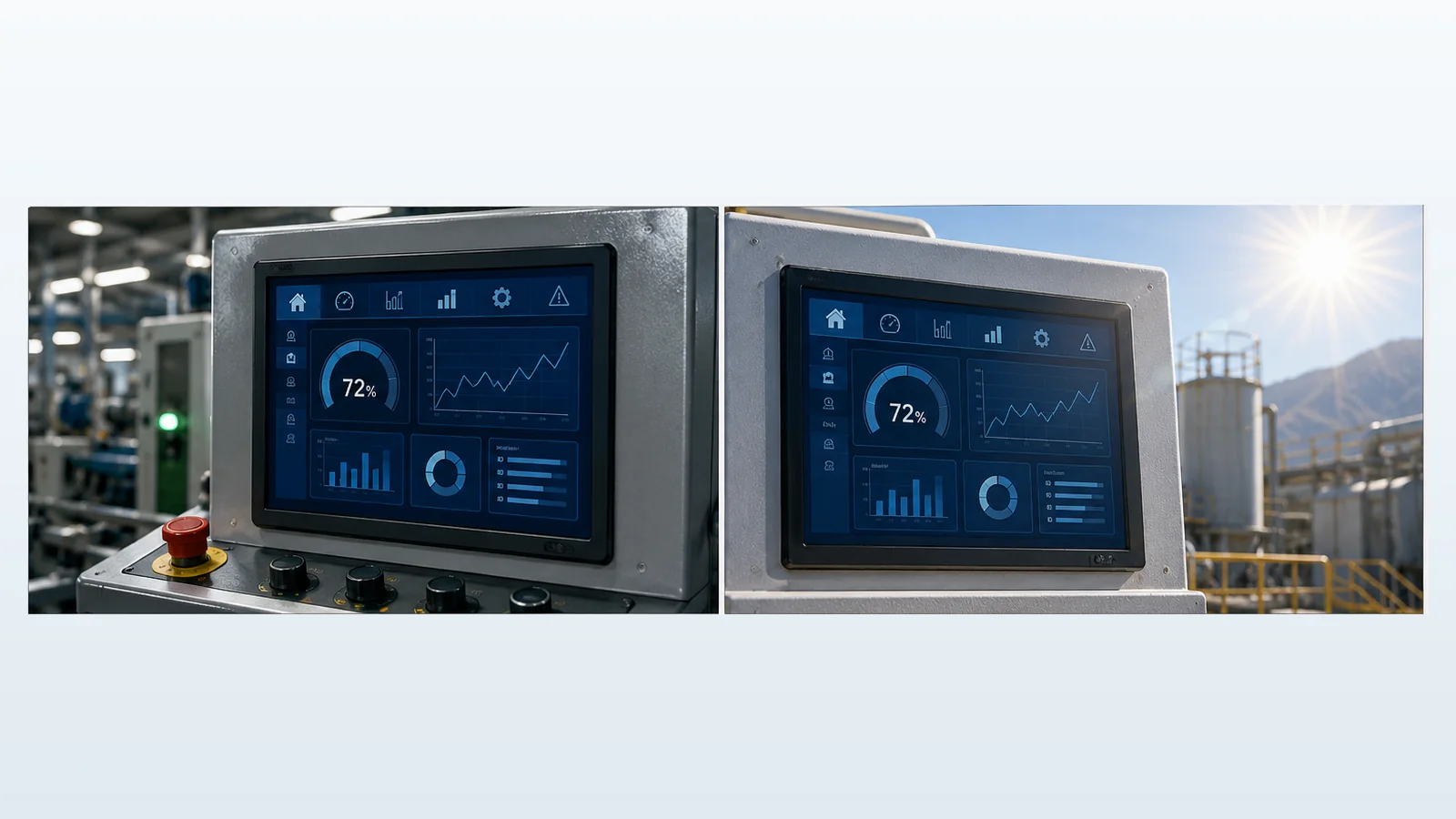
A sunlight readable TFT LCD is not defined by one brightness threshold. Readability depends on the luminance that reaches the viewer, the amount of ambient light reflected by the display stack, the contrast of the UI and the viewing geometry. A 1000 cd/m² module behind untreated glass and an air gap may perform worse than a lower-luminance module whose reflections are better controlled. For the wider module-selection workflow, use the seven-point industrial TFT LCD checklist.
Start with contrast in the real environment
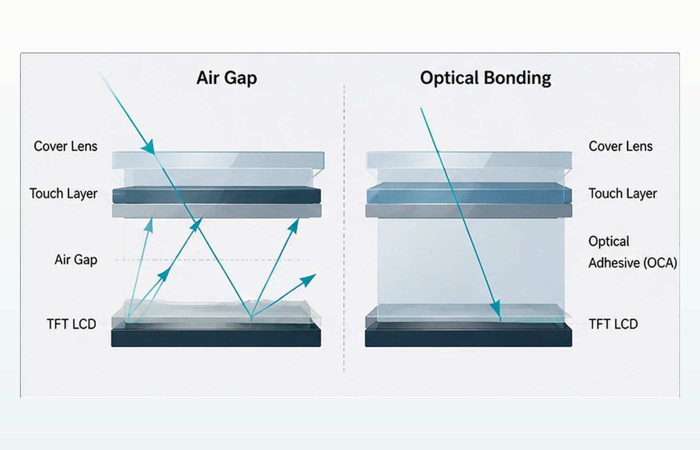
Indoors, the black state of the LCD may appear dark because ambient light is moderate. Outdoors, sunlight reflects from each optical boundary: cover surface, touch layer, air gap, polarizer and sometimes internal structures. That reflected light lifts the apparent black level. Even if the white state becomes brighter, text can still wash out when the background reflection rises too far.
Therefore, evaluate the complete assembly: LCD, touch sensor, adhesive or air gap, cover lens, coatings, printed border and enclosure angle. Also review the UI. Large text, strong color contrast and non-glossy dark backgrounds can be easier to read than thin gray details.
Brightness: necessary in many designs, but not sufficient
Backlight luminance provides the emitted-light side of the equation. TFTWorks currently lists verified examples including the DS-T035HLWSA-01 at 900 cd/m², the DS-T043BPSA-02 at 1000 cd/m² and the DS-T050BWSA-02 at 1000 cd/m². These values describe the modules; final readability must be checked after the chosen touch and cover stack is added.
Higher luminance can require more backlight current, which affects the driver, power budget, heat rise and dimming strategy. Direct solar loading can also heat a dark enclosure or cover lens. Validate both readability and temperature rather than running the backlight at maximum without a thermal plan. Use the 800 vs 1000 vs 1200 nit outdoor TFT guide to compare practical luminance classes, then review the high-brightness TFT thermal trade-offs for power, heat paths, foldback and validation.
Optical bonding: remove a major reflective interface
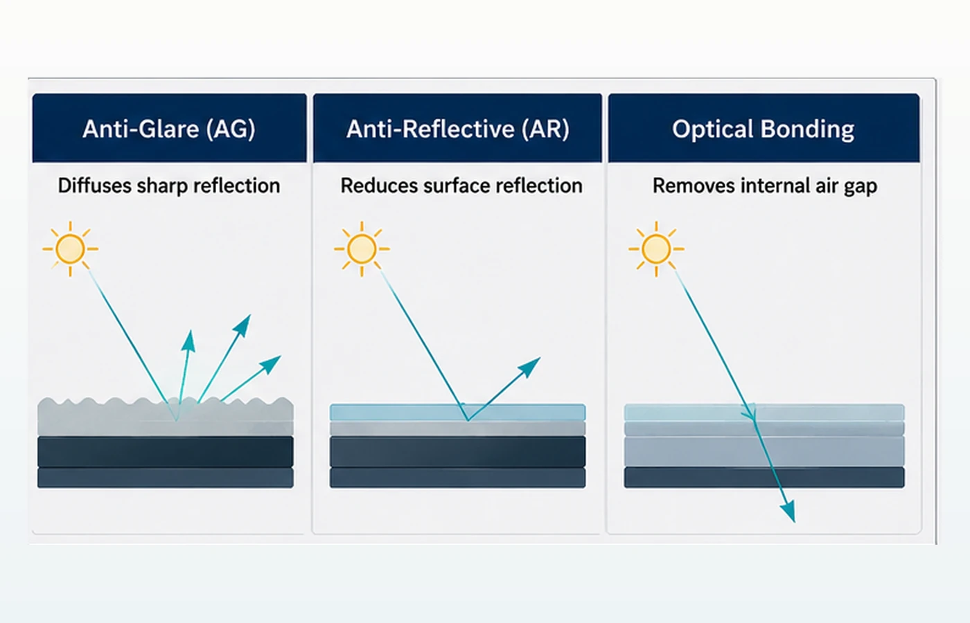
Air bonding leaves a gap between the LCD and the touch panel or cover lens. The transitions between materials with different refractive indices create additional reflections. Optical bonding fills the gap with a transparent adhesive or resin and adheres the layers. The result can improve light transmission and reduce internal reflections, especially in bright ambient conditions.
Bonding can also eliminate a cavity where condensation could appear and can make the front stack feel more mechanically unified. It is not a guarantee of outdoor performance by itself: adhesive selection, process quality, cover treatment, LCD luminance and UI contrast still matter. Use the industrial TFT optical-bonding guide to review benefits, limits, OCA/LOCA choices and validation risks.
AG and AR solve different reflection problems
Anti-glare (AG): diffuse mirror-like reflections
An anti-glare surface uses microscopic texture or a film to spread specular reflections. Instead of seeing a sharp image of the sun, lamp or operator, the viewer sees a broader, softer reflection. This can improve usability, but stronger haze can reduce perceived sharpness or create sparkle over fine pixels. Evaluate the finish at the actual pixel density and viewing distance.
Anti-reflective (AR): reduce reflection at the surface
An anti-reflective coating is designed to reduce the amount of light reflected at one or more wavelengths and angles. A good AR solution can retain a clearer surface than a high-haze AG finish, but performance depends on coating design, angle, spectrum, durability and cleaning requirements. AR coatings also need handling and cosmetic acceptance criteria. The dedicated AG vs AR vs optical-bonding comparison separates the three mechanisms and shows when they can be combined.
Anti-fingerprint (AF): a maintenance aid, not an optical substitute
AF treatment can make oils easier to remove and reduce visible fingerprints. It does not replace AG, AR or bonding. In touch HMIs, cleaning chemicals, abrasion and expected service life should be part of the surface specification.
| Option | Primary effect | Important tradeoff to verify |
|---|---|---|
| Higher backlight luminance | Raises emitted display light | Power, heat, dimming range and LED lifetime target |
| Optical bonding | Reduces internal air-gap reflection and removes the cavity | Bonding material, process, yield, repair strategy and full-stack thickness |
| AG surface | Diffuses sharp reflections | Haze, sparkle, image sharpness and cleanability |
| AR coating | Reduces surface reflection | Angle/spectrum performance, abrasion and handling |
| High-contrast UI | Increases visual separation of information | Must be tested at target luminance and viewing angle |
How to choose the stack
- Define the light condition. Record direct sun, shaded outdoor, open cab, indoor high-bay lighting and nighttime requirements separately.
- Set the thermal and power limits. Include solar loading, enclosure rise and the backlight driver.
- Choose the touch and cover structure. The display must be tested behind the final lens, ink border and bonding method.
- Choose AG, AR and AF deliberately. Request samples of the finish; do not approve by abbreviation alone.
- Test the UI at relevant angles. Include the operator’s normal position and worst credible light direction.
Verified optically bonded PCAP module examples
The modules below provide concrete starting points for different UI sizes and pixel-density requirements. The listed values come from the current TFTWorks product pages; each finished assembly still requires project-specific optical, thermal, touch and mechanical validation.
| Model | Size and resolution | Verified module values | Integration note |
|---|---|---|---|
| DS-T043BPSA-02CP | 4.3 inch 480×272 IPS | 850 cd/m² PCAP, optical bonding | Compact RGB-interface option; validate the finished cover surface and viewing condition. |
| DS-T050BWSA-02CP | 5.0 inch 800×480 IPS | 900 cd/m² PCAP, optical bonding | Higher-resolution compact option; confirm the complete touch and enclosure stack. |
| DS-T101HIEWA-01CP | 10.1 inch 1280×800 IPS | 850 cd/m² PCAP, optical bonding | LVDS option with a listed −30 to +85 °C operating range; system-level outdoor validation is still required. |
| DS-T101BFHA-01CP | 10.1 inch 1920×1200 IPS | 1000 cd/m² PCAP, optical bonding | Higher-resolution LVDS option; verify host bandwidth, power, thermal limits and the final front surface. |
Compare the broader sunlight-readable candidate list and the PCAP module category before requesting the current datasheet and approved drawing for the selected model.
A practical outdoor readability validation plan
- Measure or document ambient light at the display plane, not only general weather.
- Test the final cover lens and touch assembly, including the printed border.
- Use the intended UI, backlight setting and viewing angles.
- Check polarized sunglasses if the application requires them.
- Run hot-surface and enclosure-temperature checks under solar exposure.
- Record photos only as supporting evidence; use defined visual acceptance criteria for the engineering decision.
Technical references
- EIZO — About Optical Bonding: explains the air gap, reflection, visibility and condensation considerations.
- 3M — Anti-Glare Filter Technical Data: describes diffusion of mirror-like reflections in bright conditions.
- 3M — Industrial Display Enhancement: overview of display films, bonding materials and light-control options.