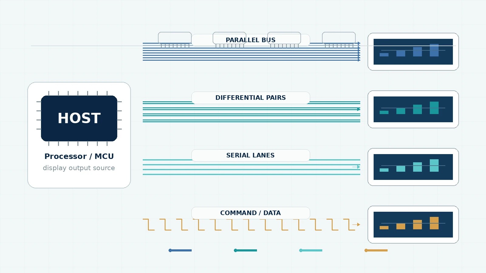
Industrial TFT modules commonly accept continuous pixel streams or host-written commands. RGB, LVDS and MIPI DSI are usually associated with video data paths; MCU interfaces let the host write commands and pixel data into a display controller. Each family can be the right choice. Problems appear when a team selects a display before confirming the host output, timing and initialization path. For the broader module shortlist, begin with the seven-specification industrial TFT LCD guide.
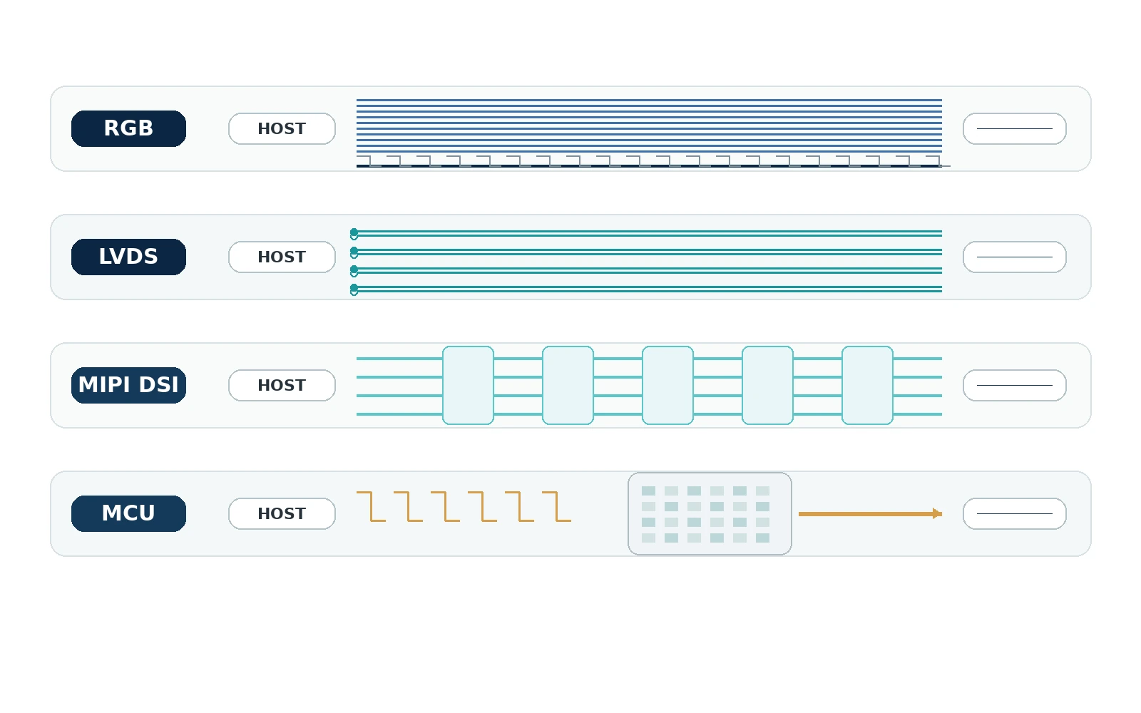
Interface comparison at a glance
| Interface | Signal approach | Typical strengths | Key items to verify |
|---|---|---|---|
| Parallel RGB (DPI/TTL) | Separate color data plus clock and control signals | Direct, predictable real-time pixel stream; common on embedded display controllers | Color depth, voltage, clock edge, sync/DE mode, porches, pinout and trace routing |
| LVDS / OpenLDI-type panel link | Pixel data serialized over differential pairs | Fewer high-speed conductors than parallel RGB; useful for higher pixel clocks and separated boards | Single/dual channel, mapping, pair polarity, clock, connector and cable impedance |
| MIPI DSI | Packetized high-speed serial display link, commonly over D-PHY | Low pin count, high bandwidth, low power and low EMI targets | Lane count, PHY support, command/video mode, initialization, DCS commands and panel firmware |
| MCU 8080/6800-style | Host writes commands and pixel data over a parallel bus | Simple control for smaller displays and partial updates; display controller often stores pixels | Bus width, write timing, controller command set, memory orientation and achievable update rate |
Parallel RGB: direct pixel timing with a wide bus
Parallel RGB sends red, green and blue data bits alongside pixel clock and control signals such as HSYNC, VSYNC and data enable. Common formats include RGB565, RGB666 and RGB888, but the names do not define the complete electrical interface.
RGB is a practical fit when the processor has a native LCD controller and the module is close to the host PCB. The host continuously generates the pixel stream, so the frame buffer and timing engine usually sit on the host side. With 24-bit RGB, the conductor count is high, and simultaneous switching plus pixel-clock edges require controlled layout. Use the dedicated RGB TFT LCD timing guide to calculate the clock, active area and blanking intervals.
Verify logic voltage, color-bit order, unused-bit handling, pixel-clock polarity, timing ranges and whether the panel uses DE-only or sync signals. Also verify initialization lines, backlight control and any separate serial control interface. TFTWorks RGB examples include DS-T035HLWSA-01 (RGB 24-bit, 54-pin), DS-T043BPSA-02 (RGB 24-bit, 40-pin) and DS-T050BWSA-02 (RGB 24-bit, 40-pin).
LVDS: serialize the pixel link over differential pairs
LVDS panel links serialize parallel pixel and control data across differential pairs. This reduces the number of high-speed conductors between the source and panel and improves noise behavior when the interconnect is designed correctly.
Do not stop at “LVDS.” Confirm channel count, pixel clock range, bit mapping, color depth, pair order, pair polarity and connector definition. Different mapping conventions can produce incorrect colors even when the link is otherwise active. Cable impedance, pair matching, return path, connector transitions and common-mode requirements matter. The LVDS cable-length selection guide explains how to define and validate the complete harness.
If the host outputs parallel RGB, an RGB-to-LVDS bridge may be possible. That bridge changes the BOM, board area, power, software and EMC work, so compare it with selecting a native interface at the start.
MIPI DSI: high-speed serial display integration
MIPI DSI defines a high-speed serial interface between an application processor and display module. It is designed for high performance, low power, low EMI and reduced pin count, but compatibility includes protocol and initialization—not only the physical connector.
Confirm that the host supports the panel’s required physical layer, lane count and lane rate; common industrial modules use DSI over D-PHY, while newer DSI-2 implementations can support additional PHY options. Determine whether the module uses command mode, video mode or a specific combination. Obtain the initialization command sequence, reset timing and sleep/wake behavior. A panel with the correct resolution and lane count may still fail if the host lacks the required commands or timing flexibility. Use the MIPI DSI lane-selection guide to calculate the payload and qualify a shared lane configuration.
MCU interface: command and pixel writes for controlled updates
An MCU-style panel typically includes a display controller with graphics RAM. The host writes commands and pixel data using a parallel 8080/6800-style bus or, on some smaller modules, a serial peripheral interface.
This architecture can suit smaller displays, menus and partial updates because the display controller retains the image. Full-screen animation at higher resolution can be limited by bus bandwidth. Calculate the data required for the target color depth and update rate, including protocol overhead, rather than relying on the maximum bus clock alone.
Verify controller IC, command set, read/write voltage, bus width, write-cycle timing, address/data control, chip select, reset and tear-signal options. Firmware dependence on a specific controller should be documented for lifecycle replacement.
MCU/SPI TFT module vs UART smart display
An MCU or SPI TFT module describes the electrical and command interface between the project host and the module's display controller. It is not automatically a UART smart display. A UART smart display normally adds its own serial protocol, HMI software and system behavior, so it is a different product-level decision.
Do not treat a module, a serial HMI product and a finished industrial monitor as interchangeable based only on diagonal size, connector or a simple serial link. For a useful engineering review, state which system boundary is required and provide the host output, target resolution, update behavior, connector constraints and operating environment.
Resolution and frame rate shape the interface decision
Active pixels are only part of a video stream. RGB and LVDS timing includes horizontal and vertical blanking. MIPI DSI adds packet and protocol behavior. MCU transfers include commands, addressing and bus cycles. Start with the native resolution, target frame rate and color depth, then use the host and panel timing tables to determine real margin.
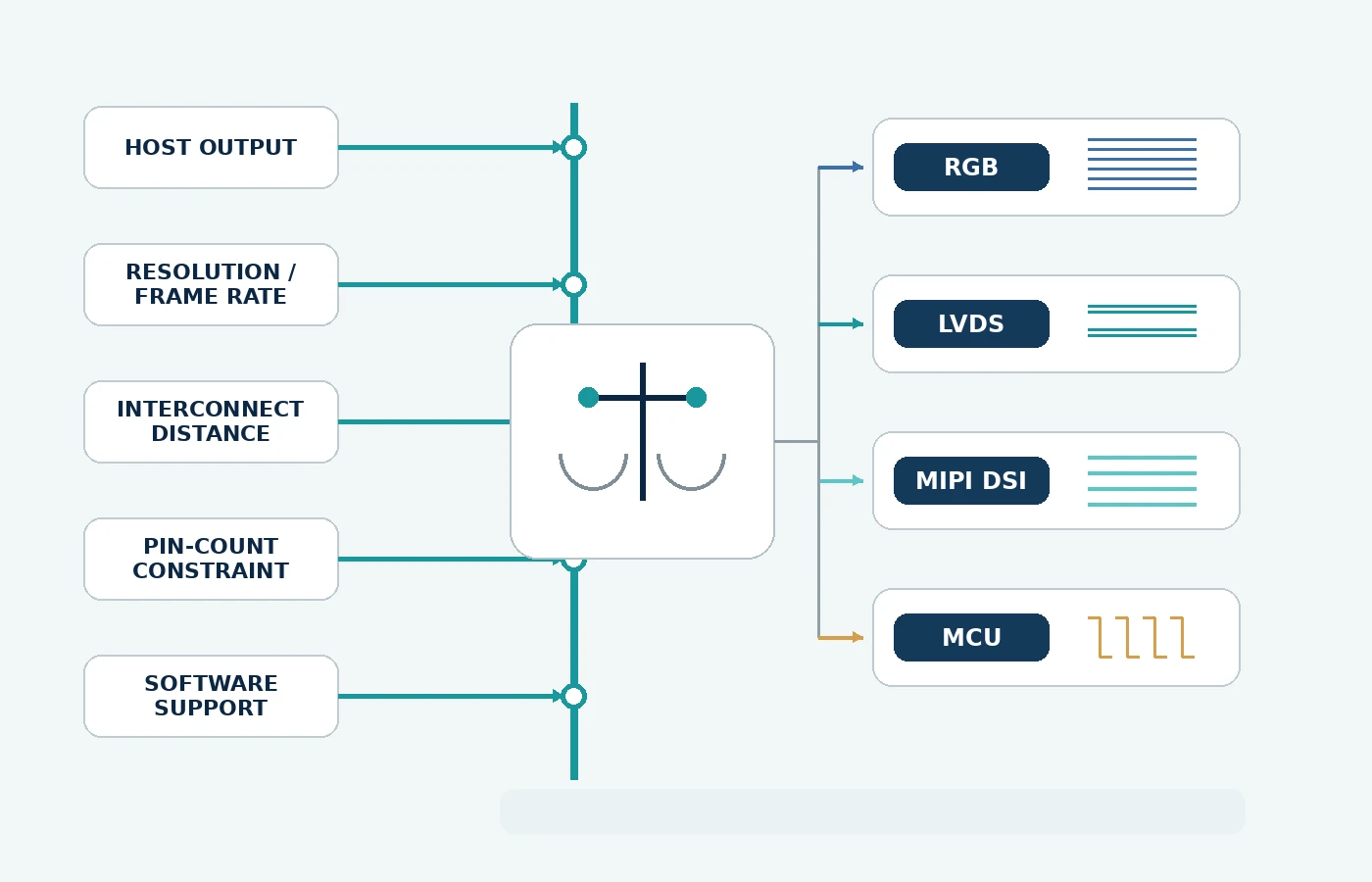
A lower-resolution HMI with mostly static screens may work well with an MCU interface. A continuously animated display may favor a native video interface. A higher-resolution panel located away from the processor may make differential serialization attractive. There is no universal size threshold; the host architecture and mechanical layout decide. If the host and panel do not share a native interface, use the TFT LCD controller-board selection guide to evaluate the complete conversion path.
Ten interface questions before you request a sample
- What exact display output does the host processor provide?
- What voltage levels and I/O standards are available?
- What native resolution, color depth and frame rate are required?
- Can the host generate the panel’s pixel timing or command sequence?
- What connector, pitch, contact side and pin mapping are required?
- How long is the interconnect, and what routing/cable constraints apply?
- Does the panel require an initialization table or controller-specific driver?
- How are reset, sleep/wake, backlight enable and dimming controlled?
- What EMC, ESD and ground-reference requirements apply?
- Can the exact interface definition be frozen in the approved datasheet and drawing?
If a standard module is optically and mechanically suitable but the tail or pinout differs, review custom TFT LCD FPC requirements and the broader TFTWorks engineering customization options.
If the display has already reached bring-up but the image is missing, shifted, unstable or corrupted, follow the industrial TFT LCD interface troubleshooting workflow and capture the evidence before changing hardware or firmware.
Technical references
- MIPI Alliance — Display Serial Interface (MIPI DSI): official overview of the high-speed serial display interface, physical layer and design goals.
- Texas Instruments — RGB to OLDI/LVDS Display Bridge Reference Design: demonstrates conversion from parallel RGB to an LVDS/OLDI panel link and discusses higher pixel-clock concerns.
- Texas Instruments — How to integrate an LCD into an HMI: overview of RGB and LVDS display connections in industrial HMI systems.