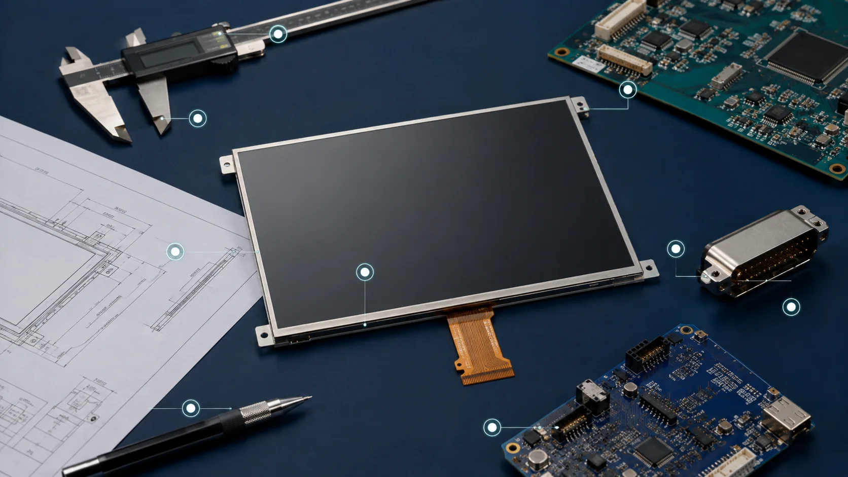
The short answer: choose an industrial TFT LCD by matching the complete display system—not only the diagonal size. The host processor, pixel format, FPC, backlight power, touch controller, front stack, enclosure and operating environment must all agree with the module specification. A disciplined selection review closes seven items: size, resolution, brightness, interface, touch, temperature and mechanical structure.
The seven specifications at a glance
| Specification | What to verify | Typical redesign risk |
|---|---|---|
| 1. Size | Active area, module outline, bezel and viewing distance | A nominally equal diagonal does not fit the opening |
| 2. Resolution | Pixel count, aspect ratio, UI assets, pixel clock and memory load | Host cannot sustain the required frame timing |
| 3. Brightness | Luminance target, ambient light, front-surface reflection, power and heat | A “high-brightness” module is still hard to read in the real stack |
| 4. Interface | RGB, LVDS, MIPI DSI or MCU; voltage, mapping, timing and pinout | Connector fits but signals are incompatible |
| 5. Touch | PCAP or RTP, controller, cover lens, gloves, water and EMC | Touch fails through the final lens or near system noise |
| 6. Temperature | Operating, storage, cold-start response, backlight and materials | Screen starts slowly or front stack is not qualified |
| 7. Mechanical structure | Outline, AA/VA, thickness, FPC route, stiffener, mounting and tolerance | Late enclosure or cable redesign |
1. Size: start with the viewing requirement, then verify the outline
Diagonal size describes only one dimension of the active display. Two “4.3-inch” modules can have different aspect ratios, border widths, FPC exits, component keep-out areas and overall thicknesses. Begin with the required information density and viewing distance, then check the active area, viewing area, module outline and enclosure opening as separate dimensions.
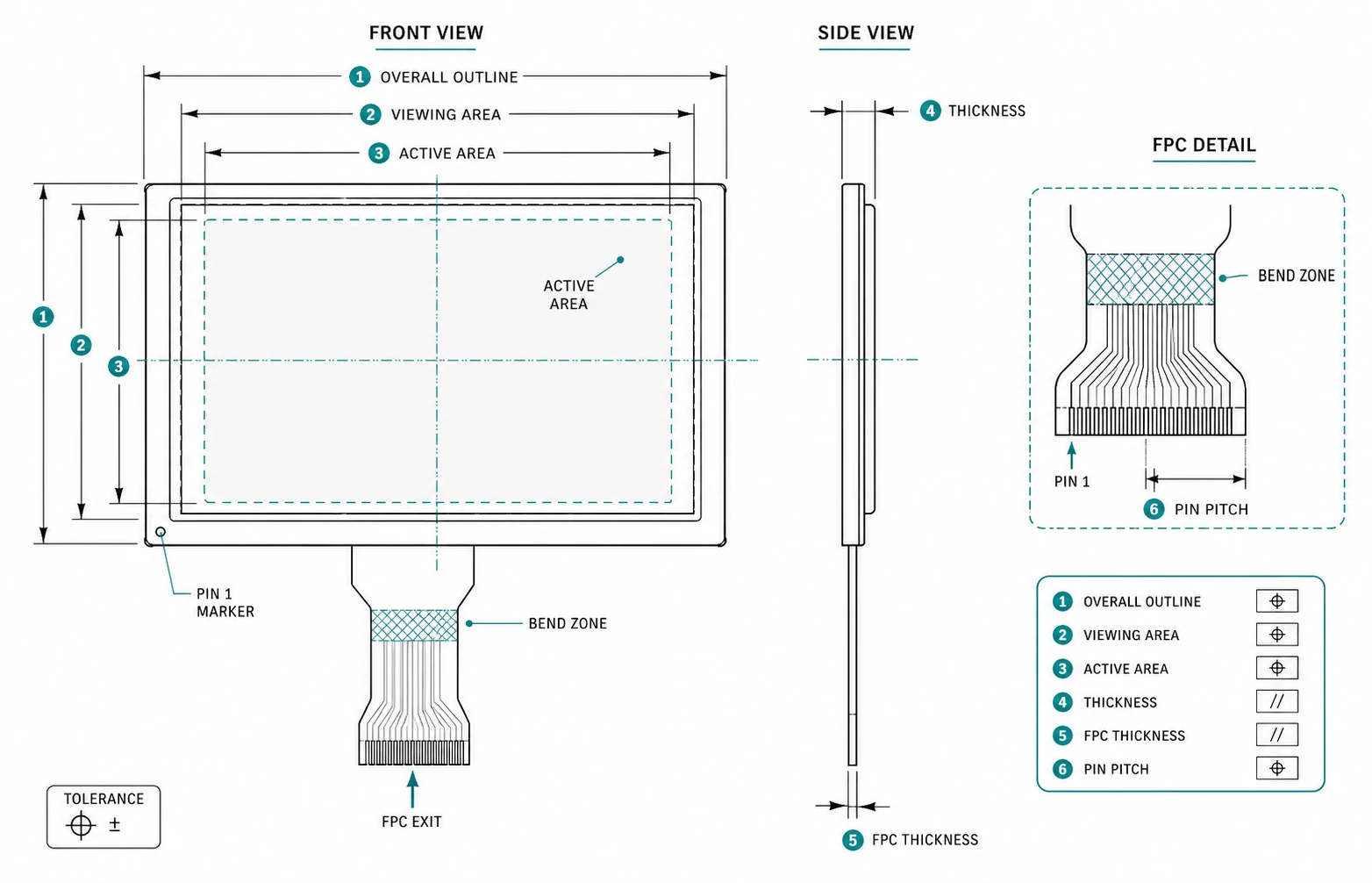
For replacement projects, overlay the candidate drawing on the legacy drawing. Check datum locations, corner radii, metal-frame tabs, connector location, FPC bend zone and the distance between the display active area and the product window. A near match may still move the image relative to the bezel. Use the obsolete industrial LCD replacement workflow to classify direct, adapted and redesign candidates.
2. Resolution: confirm both the UI requirement and host workload
Resolution determines how much information the UI can show, but it also affects frame-buffer size, pixel clock, bus bandwidth and rendering load. Confirm the native resolution and orientation. Do not assume software scaling will rescue a mismatch: scaling can soften text and increases graphics complexity.
Ask the firmware or system team to confirm the target frame rate, blanking intervals, pixel format and memory bandwidth. If the display uses a video interface, the host must generate the exact timing window in the current datasheet. If it uses an MCU-style interface, update rate depends on how quickly the host can write changed pixels.
For small-format projects, compare the practical trade-offs in the 3.5-inch 320×240 vs 640×480 guide and the 4.3-inch 480×272 vs 800×480 guide.
3. Brightness: specify the environment, not an isolated nit value
Luminance in cd/m² is important, but outdoor readability also depends on reflections from the cover glass, touch sensor and air gaps. A higher backlight can improve emitted light while also increasing power demand and thermal load. Define where the product is used—indoor factory, shaded outdoor, direct sun, vehicle cab or nighttime dimming—then evaluate the complete optical stack.
For bright environments, compare high-brightness TFT options and review sunlight-readable display considerations. The guide to brightness, optical bonding, AG and AR explains why these are separate decisions rather than synonyms for brightness, while the 800 vs 1000 vs 1200 nit comparison helps set an initial outdoor luminance class.

4. Interface: match the complete electrical definition
“RGB interface” is not a complete specification. The design still needs the color depth, pin count, voltage levels, pixel-clock edge, synchronization mode, timing values and pin mapping. LVDS requires the correct channel count, bit mapping and clock arrangement. MIPI DSI requires compatible lane count, physical layer, operating mode and initialization sequence. MCU interfaces require compatible bus width, control signals and command set.
Check the host output before shortlisting a module. A bridge board can solve some mismatches, but it adds cost, space, power, software and validation work. Use the TFT LCD interface guide, the controller-board selection guide and the interface selection overview to narrow candidates before reviewing the model pinout and timing.
5. Touch: select around the operator and the front stack
Projected capacitive touch (PCAP) supports a modern cover-lens design and multi-touch, but final performance depends on the controller, sensor, lens thickness, grounding, noise environment and tuning. Resistive touch (RTP) detects pressure and can suit single-point control with gloves or a stylus, but it has a flexible top layer and different optical and durability tradeoffs.
Define the real input condition: bare finger, work glove, medical glove, passive stylus, water droplets, cleaning fluid or deliberate operation while wet. Then define the required cover-glass thickness, printed border, touch-tail route and host interface. Compare industrial TFT modules with PCAP, resistive-touch options, the PCAP vs resistive touchscreen guide and the touch and cover-glass engineering options.
6. Temperature: separate operation, storage and cold start
Operating temperature states the range in which the approved module is specified to function. Storage temperature is a non-operating limit and cannot be used as permission to run the display. At the low end, liquid-crystal response may slow; the system must also start its power rails, backlight, touch controller and application processor correctly. At the high end, enclosure heat rise and backlight dissipation can push the module above ambient.
For demanding environments, shortlist from the wide-temperature TFT LCD category, then request behavior and validation requirements for the actual cold-start and hot-soak conditions.
7. Mechanical structure: review the drawing as a system interface
The drawing must be reviewed by mechanical, electrical and manufacturing teams. Confirm active area (AA), viewing area (VA), overall outline, total stack thickness, FPC position, bend allowance, stiffener and contact side. Add tolerance stack-up for adhesive, gasket, cover glass and enclosure. Keep pressure from the bezel away from the active area and fragile glass edges.
If the FPC or connector must change, treat it as a controlled engineering project. Pinout, power sequence, signal return paths, component placement and EMC behavior still need review. The TFTWorks engineering and customization page outlines support for FPC, interface, touch, cover glass, optical bonding and driver-board integration.
The RFQ checklist to complete before sampling
A sensible shortlist is a starting point, not design approval
A product page can help narrow the field. Final approval should use a current datasheet, controlled drawing, electrical review and physical samples in the intended system. If a standard module is close but the connector, FPC, touch stack or cover glass differs, define the change before tooling and sample release.