Short Answer
Validation has two jobs, and most projects only do the first. Job one is functional bring-up: confirm the interface mapping, timing and mechanical fit so the module works in your product at all. Job two is qualification: produce recorded evidence that this exact configuration behaves correctly at your environmental limits, through your finished front stack, at production tolerances, with more than one unit. Approval means job two is complete and the configuration — model suffix, drawing revision, datasheet revision, FPC variant, touch firmware, bonding, cover lens, backlight — is frozen in writing. Everything else is an opinion about one sample.
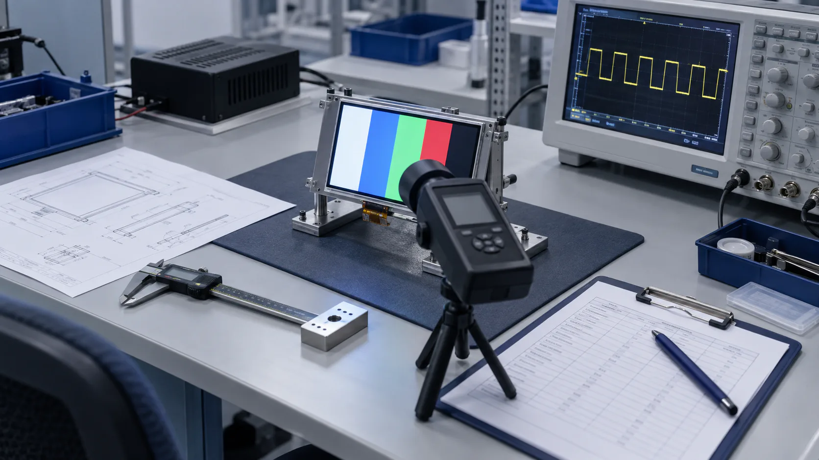
First, Freeze What You Are Approving
You cannot validate an unnamed thing. Before any test, write down the complete identity of the article under test, because every one of these can change what arrives in a production carton while the headline model number stays the same:
- Full model number including every suffix. A suffix commonly encodes touch, bonding, brightness or interface variant — the difference between a module with and without PCAP can be one character.
- Mechanical drawing revision and datasheet revision, by number and date.
- FPC or connector variant, pin count and pin definition. See the custom FPC guide for why this is its own axis of variation.
- Touch controller part and firmware version, if the module includes touch.
- Front stack construction — air gap or optical bonding, cover lens material and thickness, surface treatment.
- Backlight configuration and its drive conditions, including the PWM frequency and duty you actually intend to ship.
That list is the control record for everything that follows. Attach it to each test result. If any line changes later, you know exactly which results are still valid and which are not.
Bench or Product? Both, in Order
Bench tests on the bare module give you a clean reference: the display's own behaviour with nothing else in the way. In-product tests are the ones that decide, because the enclosure changes the thermal path, the front stack changes the optics, and the host harness changes the noise environment. Run the bench test first so that when the in-product result differs, you can tell which layer caused it.
| Bench, bare module | In product, final enclosure | |
|---|---|---|
| Purpose | Reference behaviour and fault isolation | Evidence for approval |
| Optical result | Panel luminance and contrast as supplied | What the user actually sees, after lens and reflection losses |
| Thermal result | Module self-heating alone | Real internal temperature with enclosure and neighbours |
| EMC and noise | Clean; hides most real problems | Backlight PWM, DC-DC converters, motors, harness routing |
| Mechanical result | Dimensions against the drawing | Fit, bezel overlap, stack depth, stress at mounting points |
| Touch result | Sensor and controller capability | Behaviour through the real lens, with the real grounding |
| What it cannot prove | Anything about your product | Whether a failure is the module or your integration |
Sample Size, and Why One Is Not Enough
A single unit cannot show you a spread, and several of the tests below destroy or degrade the sample. A workable minimum, all drawn from the same build so the results are comparable:
- One unit for functional bring-up and interface debug — this one gets handled, re-seated and possibly damaged.
- Three or more units for dimensional and optical measurement, so you see unit-to-unit variation rather than one lucky part.
- Dedicated units per destructive environmental sequence — thermal cycling, humidity, vibration — never reused across sequences, because the second test then measures the damage from the first.
- One reference unit kept untested, stored and labelled, as the comparison article for any future field complaint.
If the project cannot afford that many samples, the honest move is to record the sample size alongside the results rather than to report a conclusion the data cannot support.
Mechanical Verification
Measure the sample against the drawing rather than assuming they match, and measure in the assembly rather than only on the bench.
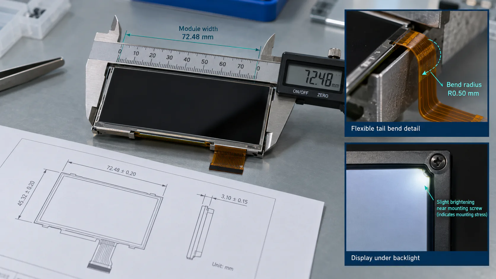
- Outline, active area, viewing area and total depth against the drawing, on multiple units, with the tolerances stated.
- Mounting hole or tab positions, and whether the fastener torque induces stress visible as a bright or dark patch on the panel — a common and easily missed defect.
- FPC exit direction, bend radius and routing in the real assembly. Check the bend at the real fold, not at a convenient one; repeated flexing at a tight radius is a field failure mode.
- Connector position and mating access with the host board installed, including whether the connector can be seated and unseated during service.
- Bezel overlap against the active area on all four sides, with the front panel aperture at its worst-case tolerance.
- Full stack depth: module plus touch sensor plus bonding or air gap plus cover lens plus gasket, against the enclosure.
- Keep-out zones respected by neighbouring components, cables and heat sources.
Electrical and Interface Verification
The trap here is that a working display feels like a validated interface. It is not. A configuration sitting at one convenient timing point can be a long way from the middle of the datasheet window, and it will fail when a temperature change or a different host batch moves it.
- Pin-by-pin confirmation against the frozen pin definition, including which pins are no-connect and which must be grounded — not inferred from a reference design for a similar part.
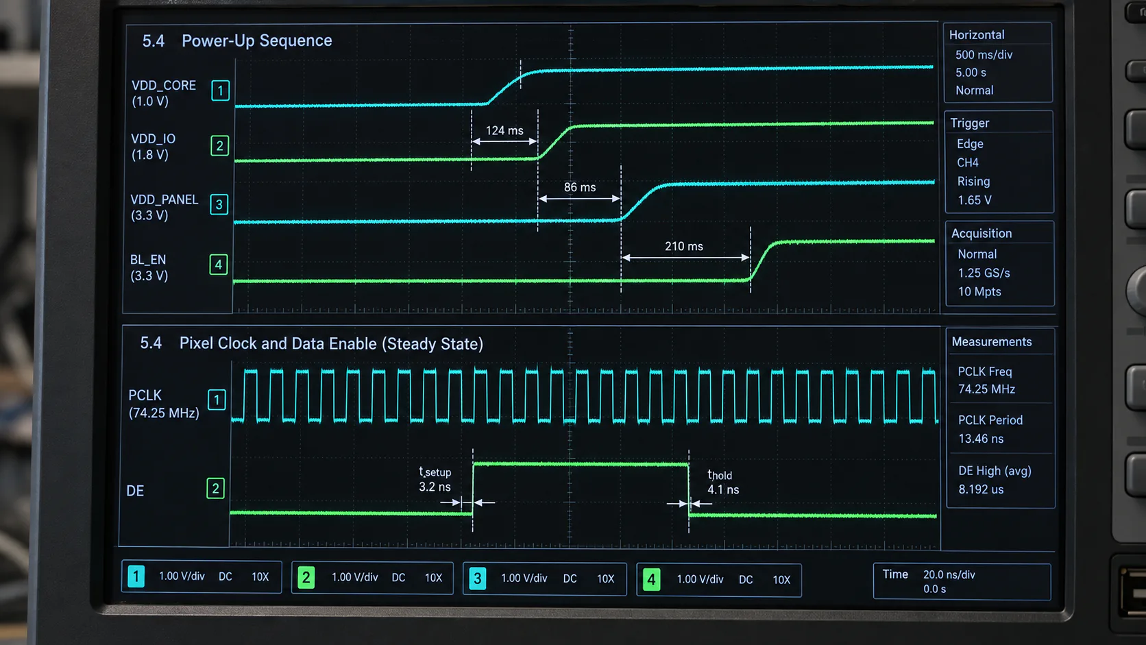
- Timing margin, not a timing point. Verify at the minimum, typical and maximum clock and blanking values in the datasheet, and confirm the image is stable throughout. The RGB timing guide and the interface troubleshooting guide cover the symptoms that indicate you are near an edge.
- Power sequencing in both directions, measured on a scope: rail order, rise and fall times, and the delay between logic and backlight. Out-of-sequence power-down is a slow killer that shows up as image sticking or reduced life.
- Supply rails at their tolerance extremes, and behaviour on brown-out and fast power cycling — not just a clean bench supply at nominal.
- Backlight drive: current regulation, PWM frequency and duty across the full dimming range, including the lowest usable setting, checked for visible flicker and audible noise.
- Harness at production length and routing, with the real connectors and the real ground return. For LVDS, review the cable-length guidance before freezing the harness; for MIPI, the lane selection notes.
- Current consumption logged at minimum, nominal and maximum brightness, at room temperature and at both temperature extremes — the cold figure is usually the surprise.
- ESD and EMC at product level with the display live, watching for image disturbance, touch misbehaviour and whether the display recovers by itself or needs a reset.
Optical Verification
Optical results measured on a bare module describe a component you are not shipping. Measure through the finished front stack, in the real geometry.
- Luminance at centre and at the nine standard grid positions, with the instrument, distance and aperture recorded. Report the uniformity as a number.
- Luminance through the final front stack and the loss relative to the bare module. Every added layer costs light; know how much before you promise a brightness figure.
- Contrast in the real ambient, including the worst case — a window behind the operator, a work light overhead. A high panel contrast ratio measured in a dark room says little about a bright room.
- Reflection behaviour of the finished surface, and whether an anti-glare or anti-reflective treatment behaves as intended once bonded. Background in the AG vs AR vs bonding comparison.
- Viewing angles at the installed mounting angle, seated and standing, including any colour or contrast shift the operator will actually meet.
- Colour and white point against the specification, and consistency across the sample set — visible variation between units on a production line becomes a complaint.
- Defect inspection to an agreed criterion: bright and dark pixel counts and clustering, Mura, edge light leakage, newton rings in an air-gap stack. Agree the acceptance criteria in writing before approval, not during the first quality dispute.
- Backlight lifetime evidence — the test conditions, the luminance endpoint used and the duty cycle assumed. The backlight lifetime guide explains why a bare hour figure is not a specification.
Environmental Verification
These are the tests that get skipped when the schedule slips, and they are the ones that prevent the failures nobody can fix after launch.
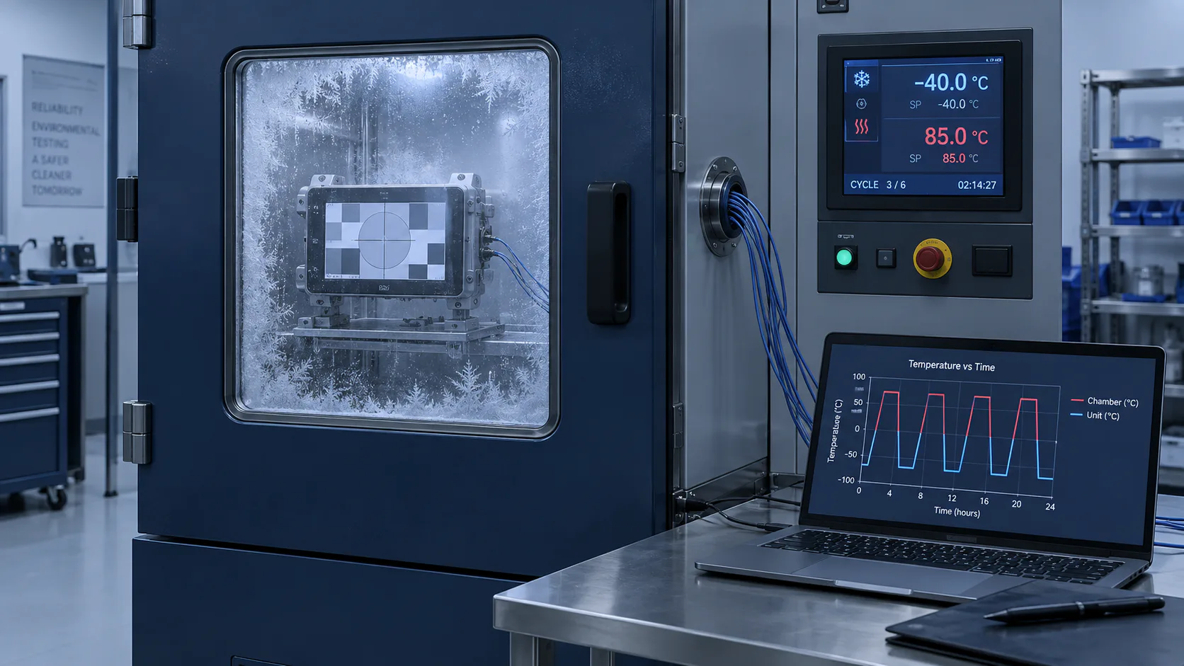
- Powered operation at both temperature limits, in the enclosure, until the internal temperature stabilises — with the internal temperature logged next to the display, not the chamber setpoint.
- Cold start from the minimum specified temperature, timed. Record how long until the image is usable and whether the backlight and logic come up in the right order when cold, which is where the response-time and forward-voltage effects in the wide-temperature guide appear.
- Storage-range excursion followed by a return to operating temperature and a functional check — shipping and unheated warehousing are storage conditions, and the storage range is sometimes narrower than people assume.
- Thermal cycling across the operating range for the cycle count your qualification plan calls for, with functional and optical checks before and after, on dedicated units.
- Humidity and condensation, including a deliberate dew-point excursion if the product will meet one, with inspection for moisture behind the display and at the FPC bonds.
- Vibration and mechanical shock at product level, then inspection for connector backout, FPC damage, backlight rattle and internal displacement.
- Chemical and cleaning exposure where relevant — see the washdown design guide, and note that ingress ratings belong to your enclosure and not to the module.
- Extended burn-in with a static high-contrast pattern at the maximum operating temperature, inspected for image sticking and Mura.
Touch Verification
If the product has a touchscreen, it needs its own test plan. The sensor is tuned to a specific cover lens, and the tuning does not survive a change in lens material or thickness.
- Accuracy and linearity across the whole surface, with attention to the edges and corners where error is largest.
- Multi-touch count and tracking, including two fingers close together and a drag that crosses the sensor edge.
- Every intended input condition, named: bare finger, the actual glove types, a stylus, a wet finger, a wet surface. "Gloved operation" is not a testable requirement until the glove is specified.
- Rejection behaviour: palm, forearm, water film, droplets, and a cleaning cloth, with false-input counts recorded rather than described.
- Noise immunity with the backlight at every PWM setting and with the product's own charger, motor drives and DC-DC converters running — then repeated with an external charger connected, which is where most late-stage touch problems originate.
- Behaviour at the temperature extremes, and immediately after a cold start when the panel and lens are still cold.
- Grounding verified as built, with the sensor's reference path and the user's return path both traced. The reasoning is in the PCAP design guide.
- Controller firmware version recorded, and a written agreement about notification if it changes.
The Approval Sequence
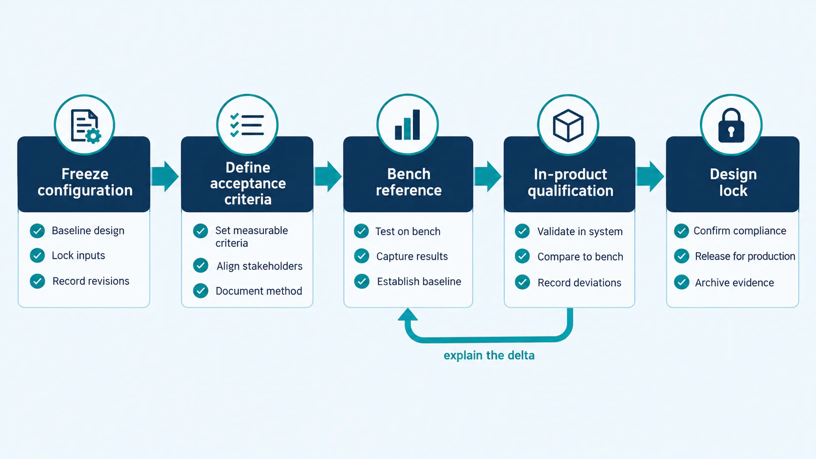
- Freeze the configuration and attach the document revisions to the test plan.
- Define acceptance criteria for every measurement, including the pixel-defect and Mura criteria, before any test runs.
- Bring up on the bench: pin mapping, timing, power sequence, backlight drive.
- Measure the bare module for dimensions and optics — this is your reference.
- Integrate into the product with the real front stack, harness and enclosure.
- Re-measure in product, optics and thermals, and quantify the difference from the bench reference.
- Run the environmental sequence on dedicated units, with functional and optical checks before and after each.
- Run the touch plan, including the noise cases with chargers and motors live.
- Review the deltas. Anything that moved between bench and product needs an explanation, not a tolerance.
- Lock the design: record the approved configuration, the evidence, the sample identities and the change-notification agreement. Store the untested reference unit.
What to Record, and Why It Matters Later
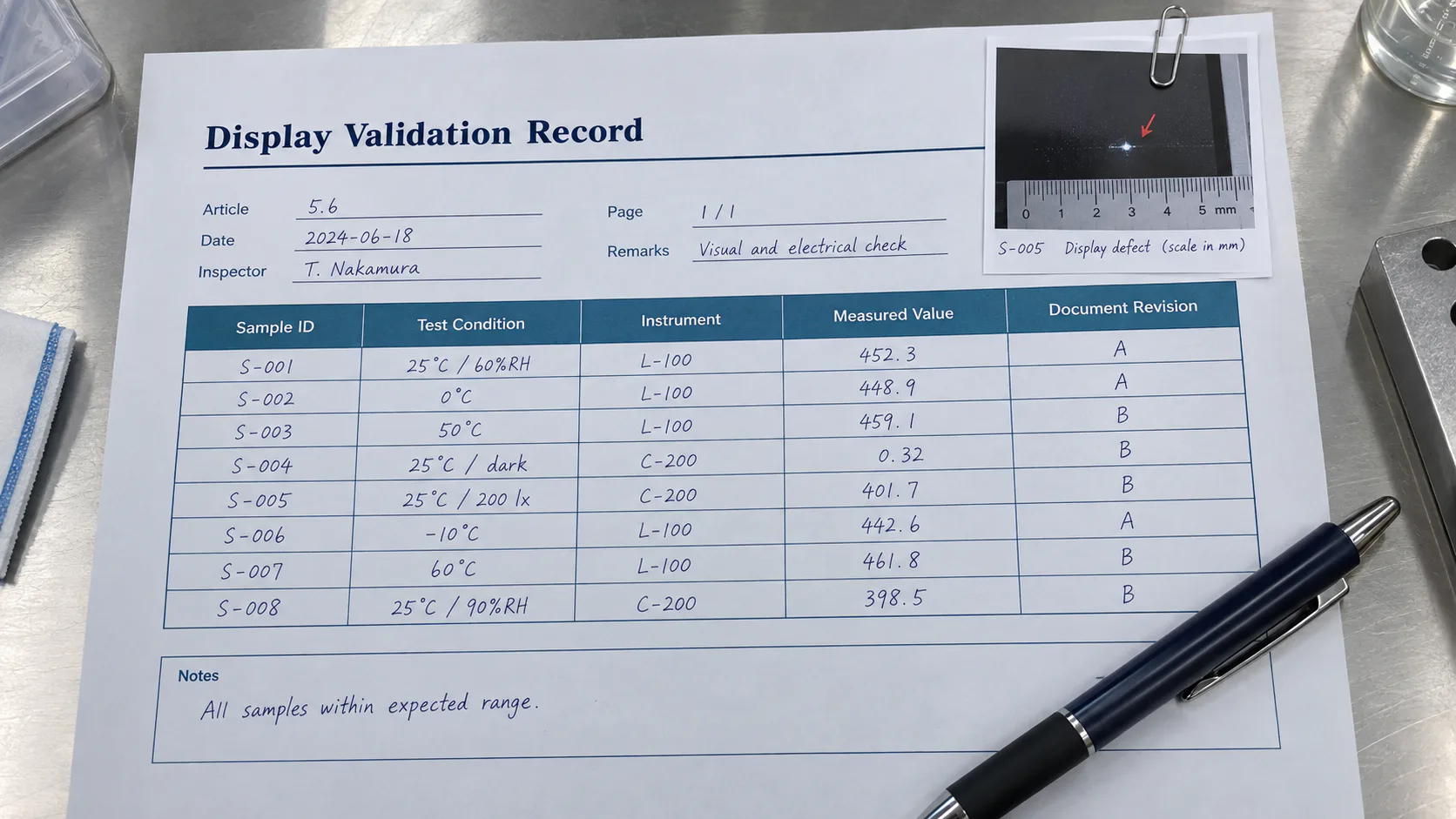
The output of validation is a document someone can use in two years to answer "is this batch different, or was it always like this?" A pass mark cannot answer that. Record for every test: the sample serial or batch identity; the exact conditions including temperature and supply voltage; the instrument and its settings; the measured value, not just the verdict; photographs of any defect with a scale reference; and the document revisions in force. When a field complaint arrives, recorded numbers let you separate drift from a bad unit, and they let a supplier investigate something specific rather than guess.
This is also where a replacement project differs from a new design. If you are qualifying a module against an existing one, the comparison must be controlled on all four axes at once — mechanical, electrical, optical, environmental — which is the argument made in the obsolete LCD replacement guide. A part that matches on three axes and differs on the fourth is not a drop-in.
Scope of this checklist. This is an engineering working method, not a substitute for the qualification standards that apply to your equipment, industry or market. Test counts, cycle numbers, acceptance criteria and safety or regulatory testing must come from your own qualification plan and the applicable standards. No certification, rating or test result is claimed here for any TFTWorks product; all product specifications must be confirmed against the current datasheet and approved drawing for the exact part.
FAQ: Display Sample Validation
How many samples do I need?
Enough that one good unit cannot hide a spread. A practical minimum from the same build: one for functional bring-up, three or more for dimensional and optical measurement, dedicated units for each destructive environmental sequence, and one untested reference unit kept for future comparison.
What exactly gets frozen at design lock?
The complete model number with every suffix, the drawing revision, the datasheet revision, the FPC or connector variant, the touch controller and its firmware version, the bonding or air-gap construction, the cover lens specification and the backlight configuration. A model number on its own is not a frozen configuration.
Isn't a working sample enough to approve the display?
No. Powering up proves the interface mapping and basic compatibility. It says nothing about behaviour at the temperature limits, luminance through the finished front stack, fit at production tolerances, timing margin across the datasheet window, or unit-to-unit consistency — each of which needs a deliberate test with a recorded result.
Should I test the module or the finished product?
Both, in that order. Bench tests on the bare module isolate the display's own behaviour and give a clean reference for fault-finding. In-product tests are the evidence for approval, because the enclosure changes the thermals, the front stack changes the optics and the harness changes the noise environment.
What records should validation leave behind?
Sample identity, exact test conditions including temperature and supply voltage, instrument and settings, measured values rather than pass marks, photographs of defects with a scale reference, and the document revisions in force. Those records are what let you distinguish drift from a bad unit when a complaint arrives later.
If you are earlier in the process, the requirements checklist covers what to gather before a module is even shortlisted, and the factory and quality page describes what we can provide alongside a sample. To start a review, browse the industrial TFT catalogue or send your requirement.