Short Answer
PCAP works by sensing a change in capacitance through everything between the finger and the sensor. So four decisions, all of them outside the display module, decide whether it works: how much dielectric sits above the sensor (cover material, thickness and ink step), what is doing the touching (bare finger, nitrile, leather, winter glove, stylus, wet finger), how well the user and the system share a reference (grounding), and what electrical noise is in the enclosure (backlight dimming, switching supplies, chargers, motors). Specify those four before the touch stack is quoted, and validate the finished assembly rather than the module.

What You Are Actually Buying
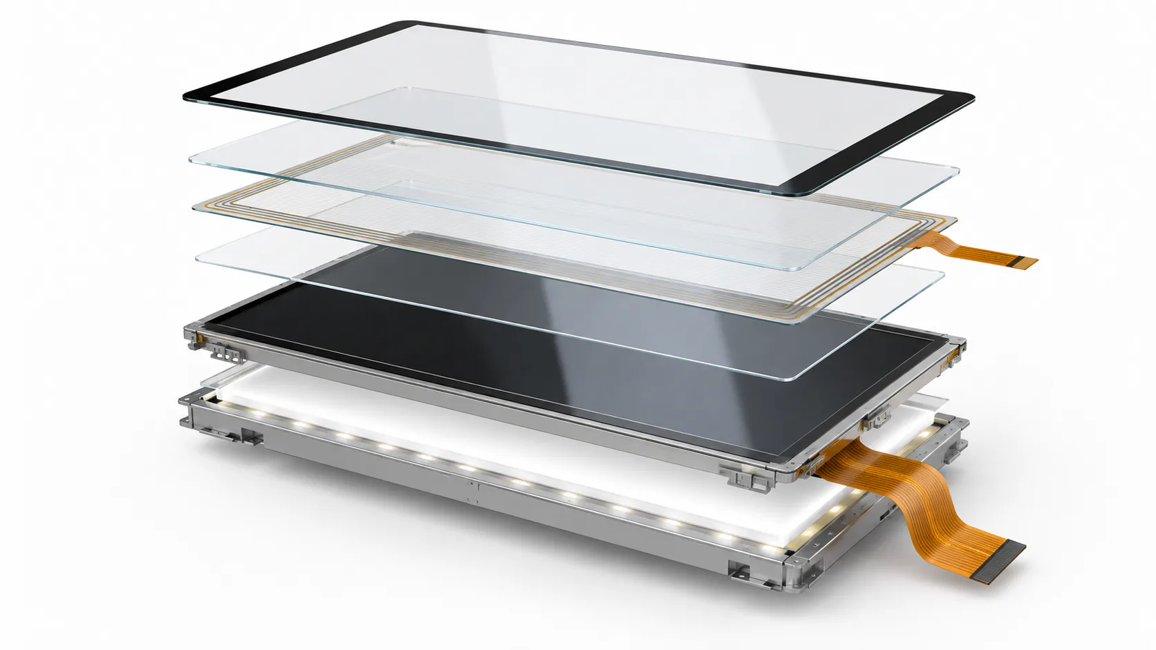
A PCAP touch module is three things: an etched sensor pattern (commonly ITO or a metal mesh on glass or film), a touch controller IC, and a firmware configuration that tells the controller how to interpret what the sensor reports. Our own capacitive-touch modules name that controller explicitly — ST1633i on the 3.5-inch and 5-inch parts, ILI2310 on the 4.3-inch, ILI2511 on the 10.1-inch parts — because it is the controller and its configuration, not the glass, that determines what the touchscreen can be tuned to do.
The important consequence: the third item, firmware configuration, is matched to a specific stack. Change the cover lens thickness, change its material, add a gasket that grounds differently, or mount the assembly in a plastic instead of a metal front panel, and the configuration that was validated no longer describes your product. This is the single most common cause of "the sample worked, production doesn't".
The Cover Lens Is Part of the Sensor
Capacitive coupling falls off as the dielectric distance between the finger and the sensor grows, and it depends on the material as well as the thickness. Soda-lime and chemically strengthened glass have a relative permittivity of roughly 6 to 8; PMMA is roughly 2.6 to 3.7, and polycarbonate is similar. In practical terms a 2 mm acrylic window presents a weaker coupling than 2 mm of glass and behaves more like a thicker cover, before you account for the fact that acrylic flexes under a firm press and glass does not.
| Decision | What it changes for touch | What to specify |
|---|---|---|
| Material (glass vs PMMA / PC) | Different permittivity, so equal thickness gives unequal coupling; plastics flex and scratch differently | Material and grade, not just "plastic window" |
| Thickness | Primary driver of signal strength; interacts with glove and water requirements | Nominal thickness and tolerance, fixed before tuning |
| Printed ink border | Ink builds a step at the edge; a step under the sensor area creates a local gap and weak edge response | Ink layer count, step height and where the printing stops |
| Edge-to-active distance | Touch accuracy degrades near the sensor border; a tight bezel places buttons in the worst region | Keep-out between the artwork window and the sensor edge |
| Air gap vs optical bonding | Bonding removes an internal reflective surface and a condensation volume; the adhesive layer becomes part of the dielectric stack | Bonding type and total stack thickness with tolerance |
| Surface treatment (AG / AR) | Optical, not electrical — but it changes the feel of a gloved drag and how visible fingerprints and water films are | Treatment type and the cleaning regime it must survive |
There is no universal maximum cover thickness. Thin covers are easy; as the cover gets thicker the sensor pattern and firmware have to be designed for it, and thick cover plus thick glove is the hardest combination in the whole discipline. Whether bonding is right for your stack is an optical and mechanical decision first — the optical bonding guide covers that side.
Gloves: Name the Glove
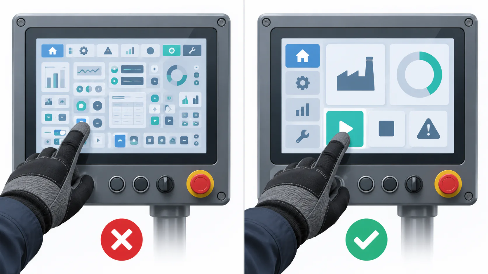
"Glove operation" is not a requirement — it is a category. A 0.1 mm nitrile examination glove is electrically almost invisible and rarely causes trouble. A 1 mm leather rigger glove adds a real dielectric layer and spreads the contact area. A padded winter glove can add several millimetres and is a different problem again. Conductive-tipped gloves behave almost like a bare finger and are the cheapest fix available if the site will accept them.
Sensitivity is the lever, and raising it is not free. A configuration tuned so that a thick glove registers will also register a water droplet, a drip of condensation, or a sleeve brushing the panel. This is the fundamental tension of industrial PCAP, and it is why the requirement has to arrive as a pair: which glove, and what else is expected to be on the surface at the same time.
Water: Four Different Problems
Water is not one condition. Separate them, because the mitigation differs:
- Droplets. Discrete drops produce localised signal that can read as touches. Mutual-capacitance sensing with a rejection algorithm handles this best, because a drop's signature differs from a finger's.
- A continuous film. A sheet of water across the surface couples a large area at once and can suppress or smear real touches. Harder than droplets.
- A wet finger, or a finger under running water. The finger is connected to a grounded water path; the signal becomes large and poorly localised.
- Cleaning and washdown. Spray plus a gloved hand plus detergent, often deliberately wiping across the panel. This is where unwanted actuation causes real incidents, and it is worth designing a lockout mode rather than relying on rejection alone. See the washdown HMI design guide for how the sealing and cleaning requirements interact.
Self-capacitance sensing is more sensitive at distance but cannot distinguish multiple simultaneous contacts and tolerates water poorly. Mutual-capacitance sensing is the normal industrial choice because it supports true multi-touch and gives the controller enough information to reject water-like signatures. Whether a specific controller offers a glove mode, a water-rejection mode, or automatic switching between them is a property of that controller and its firmware build — confirm it for the exact part rather than assuming it.
Grounding: the Half of the Circuit Nobody Draws
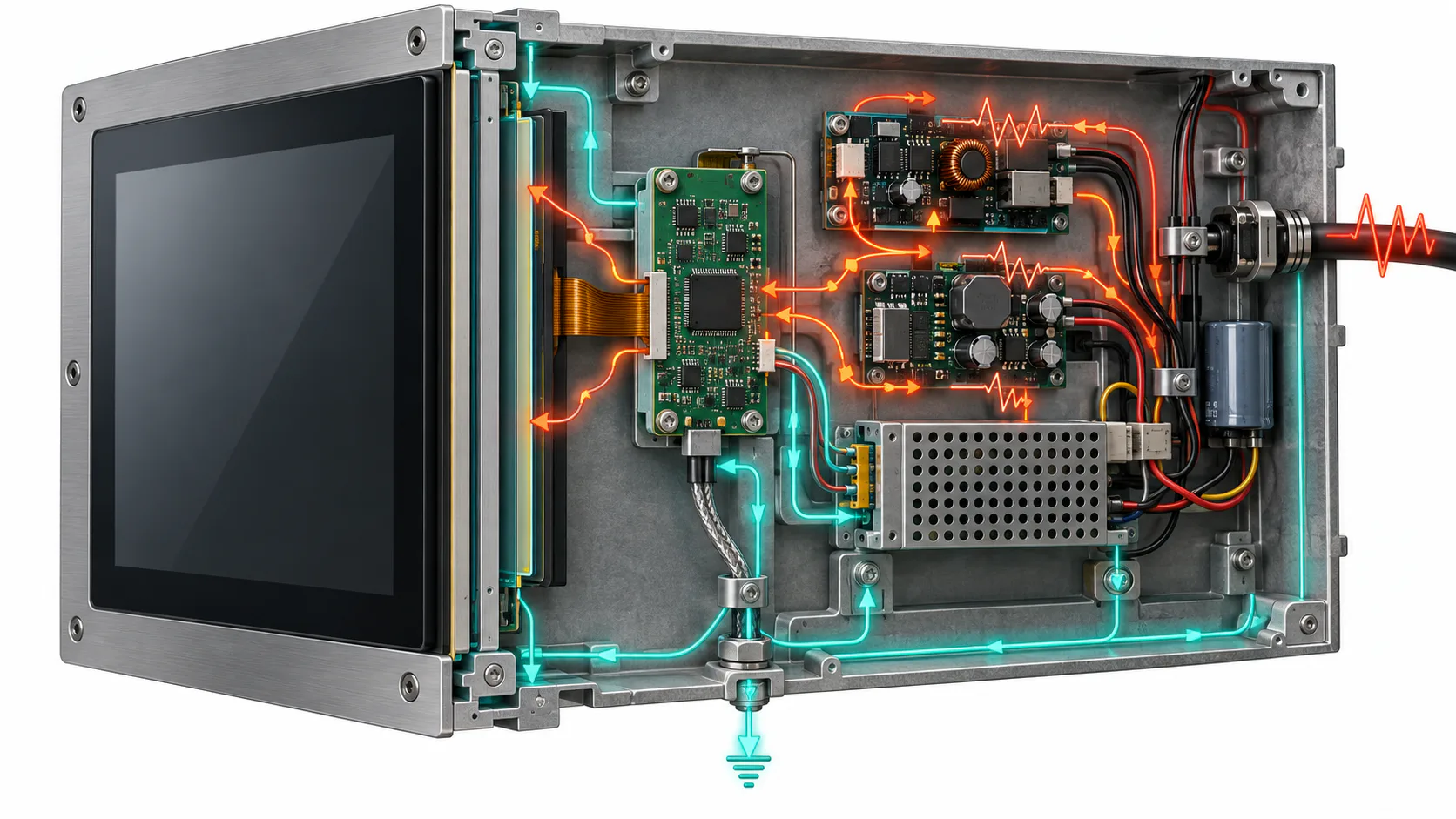
A capacitive touch measurement needs a return path. The user is coupled to earth, the system is coupled to earth, and the quality of that shared reference sets how much signal the controller sees. Three situations routinely degrade it:
- Floating equipment. A battery-powered handheld in a plastic case, or a machine mounted on rubber isolators, has a weak reference. Sensitivity drops and behaviour changes between a device sitting on a bench and one held in the hand.
- An unbonded front panel. A metal bezel that is not properly tied to the system ground can act as a floating conductor beside the sensor instead of a shield.
- Operators in insulating PPE. Rubber boots on a dry floor genuinely change the measurement, and it is a common reason a panel that passed in the lab is marginal on the line.
Design the reference deliberately: a defined, low-impedance path between touch ground, display ground and chassis; a grounded conductive frame or gasket around the sensor where the mechanical design allows; and a decision about whether the front panel is part of the shield or part of the problem.
EMC and Noise Inside Your Own Box
Most touch noise complaints are self-inflicted, and three sources account for the majority.
Backlight dimming
PWM dimming injects a square wave into the module at a frequency you chose. If it, or a harmonic, lands near the touch scan frequency, the result is jitter or phantom touches that appear only at certain brightness settings — a distinctive symptom that points straight at the cause. Changing the PWM frequency, or moving to a different dimming scheme, is usually the cheapest fix.
Switching supplies and chargers
The classic report is "touch is fine on battery, erratic on the charger". The charger's switching noise appears between the user and the sensor because the reference moved. This is a grounding and filtering problem, not a touch-module defect, and it must be reproduced with the real power supply during validation.
Layout and routing
The touch tail running alongside the display FPC or over the backlight driver picks up exactly what you would expect. Keep the touch tail short, away from the backlight and supply, and over a clean reference. ESD is the mirror image of the same geometry: the cover-lens edge and any gap at the bezel are the entry paths, so the discharge route to chassis has to be designed rather than discovered in the EMC lab.
A Design Sequence
- Write the use condition. Named glove types with thickness, the water condition, whether cleaning happens with the screen live, stylus use and whether one-finger or multi-touch is required.
- Fix the cover lens — material, thickness, tolerance, ink step, artwork window and keep-out to the sensor edge — before the touch stack is quoted.
- Decide bonding versus air gap on optical, condensation and mechanical grounds, then feed the resulting stack thickness back into the touch specification.
- Design the ground. Define the bond between touch ground, display ground, front panel and chassis, and decide how the user is referenced.
- Choose the backlight dimming scheme and record the PWM frequency as a controlled parameter, not a firmware default.
- Confirm the controller's available modes for the exact part and firmware build — glove, water rejection, automatic switching, report rate, palm rejection.
- Place the UI to suit the sensor. Keep critical targets away from the border region and size them for the worst glove, not the bare finger.
- Freeze the configuration — firmware version, sensitivity parameters and stack drawing — as one document before sampling.

Validation Checklist
Every item below is run on the assembled product — real cover lens, real enclosure, real grounding, real power supply, real firmware. A bare module on a bench proves nothing about any of it.
- Glove matrix. Each named glove type, at the four corners, the four edge midpoints and the centre. Record misses and offsets, not just pass or fail.
- Water matrix. Droplets, film, wet gloved finger, and a cleaning wipe with the screen live. Record false touches per minute.
- Linearity and edge accuracy. Drag a straight line across the full width and height; look for deviation near the border and any dead band under the ink step.
- Grounding variations. Test on and off mains, on and off charger, on an isolated bench and installed in the real frame.
- Backlight sweep. Test at 0 %, 25 %, 50 % and 100 % dimming — noise problems often appear only at specific duty cycles.
- Temperature. Repeat the core tests at both temperature extremes; sensitivity and baseline tracking both move with temperature.
- ESD. Discharge to the cover lens face, the lens edge and the bezel seam at the levels your product must meet, and check for lock-up as well as for false input.
- Recovery behaviour. Confirm the controller re-baselines correctly after a wet event, after a power cycle and after a touch held at power-on.

Our PCAP Modules
These are the capacitive-touch modules in our standard list, with the controller named. They are a starting point for a stack discussion; the cover lens, bonding and tuning are still project decisions.
| Model | Size / resolution | Luminance | Interface | Touch controller | Bonding | Operating |
|---|---|---|---|---|---|---|
| DS-T035SGV-01CP | 3.5″ 640×480 IPS | 320 cd/m² | RGB 24-bit, 54-pin | ST1633i | Optical bonding | −20 to 70 °C |
| DS-T043BPSA-02CP | 4.3″ 480×272 IPS | 850 cd/m² | RGB 24-bit, 40-pin | ILI2310 | Optical bonding | −20 to 70 °C |
| DS-T050BWSA-02CP | 5.0″ 800×480 IPS | 900 cd/m² | RGB 24-bit, 40-pin | ST1633i | Optical bonding | −20 to 70 °C |
| DS-T101HIEWA-01CP | 10.1″ 1280×800 IPS | 850 cd/m² | LVDS 6/8-bit, 40-pin | ILI2511 | Optical bonding | −30 to 85 °C |
| DS-T101BFHA-01CP | 10.1″ 1920×1200 IPS | 1000 cd/m² | LVDS 2-channel, 45-pin | ILI2511 | Optical bonding | −20 to 70 °C |
If the input method itself is still open — for example where heavy gloves, standing water and a low unit price all apply at once — start with the PCAP versus resistive comparison and our resistive touch modules before committing to a capacitive stack.
On the figures in this article. Model data — resolution, luminance, interface, touch controller, bonding type and temperature range — is taken from our published module data and must be confirmed against the current datasheet for the exact part. Permittivity values for glass and plastics are typical material ranges, not specifications. No glove-mode, water-rejection, ESD or IP performance is claimed for any product; those are properties of a finished, tuned and tested assembly.
FAQ: Designing an Industrial PCAP Touchscreen
How thick can the cover glass be?
There is no universal figure. Workable thickness depends on the sensor pattern, the controller, the firmware tuning, the system grounding and whether gloves or water are also required. Thin covers are straightforward; thicker covers have to be designed for, and thick cover plus thick glove is the hardest case. Fix the cover specification before the stack is quoted, then validate that exact combination.
Does acrylic behave like glass of the same thickness?
No. Glass has roughly twice the relative permittivity of PMMA, so the same thickness of acrylic couples less signal and behaves like a thicker cover. Acrylic also flexes under a firm press, which changes an air-gap stack. A material change is a re-tune, not a substitution.
Can one configuration do both gloves and water?
They pull in opposite directions: gloves want more sensitivity, water wants more scepticism. Some controllers offer selectable or automatic modes, but the combination must be confirmed for the specific controller and firmware build and then tested with the actual gloves and the actual water condition.
Why does touch only misbehave with the charger connected?
Almost always grounding and noise rather than a touch fault. A weakly referenced system lets supply switching noise appear between user and sensor. Fix the bond between touch ground, display ground and chassis, review the touch tail routing, and check the backlight PWM frequency against the touch scan rate.
Where should critical buttons not go?
Along the sensor border. Accuracy is weakest at the edge, the printed ink step sits there, and it is the region a gloved hand approaches at the shallowest angle. Keep confirmations, emergency functions and small targets away from the outer margin, and size everything for the worst named glove.
For the wider HMI context — mounting, viewing distance and the rest of the front panel — see the industrial HMI application notes, or send your cover-lens drawing and glove list for a stack review.