Define the input method
Document bare-finger, glove, water, cleaning and stylus conditions before choosing between PCAP and resistive touch.
Compare PCAP display modules by optical, electrical and mechanical fit, then define the touch stack around the real use environment.
Start with the cover lens, user interaction and environment, then confirm the touch controller, bonding stack and host interface. Use our PCAP versus resistive touchscreen guide when the input method is still open, and review the optical-stack guide when bright ambient light is part of the requirement.
PCAP suitability is determined by the complete touch stack, not by the sensor alone. Confirm the finished cover-lens stack, touch-controller communication, grounding, EMC conditions and enclosure tolerances before sample release.
Document bare-finger, glove, water, cleaning and stylus conditions before choosing between PCAP and resistive touch.
Cover-glass thickness, artwork, bonding and enclosure tolerances affect both the user interface and the integration route.
Touch-controller communication, power, grounding and EMC constraints require confirmation against the selected module documentation.
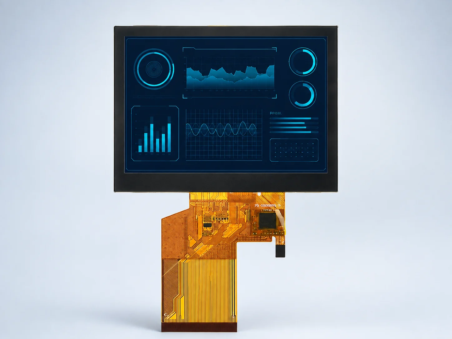

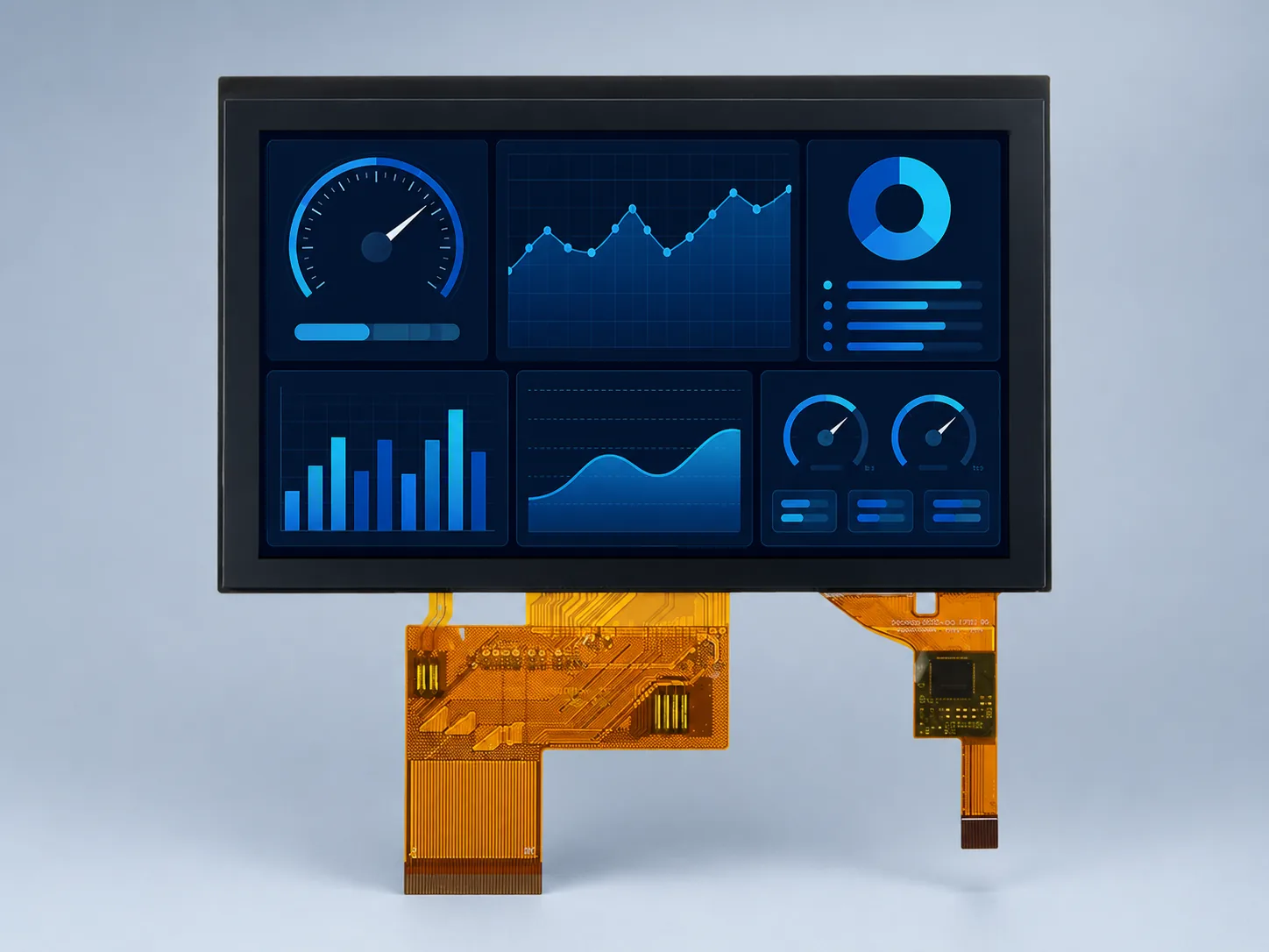
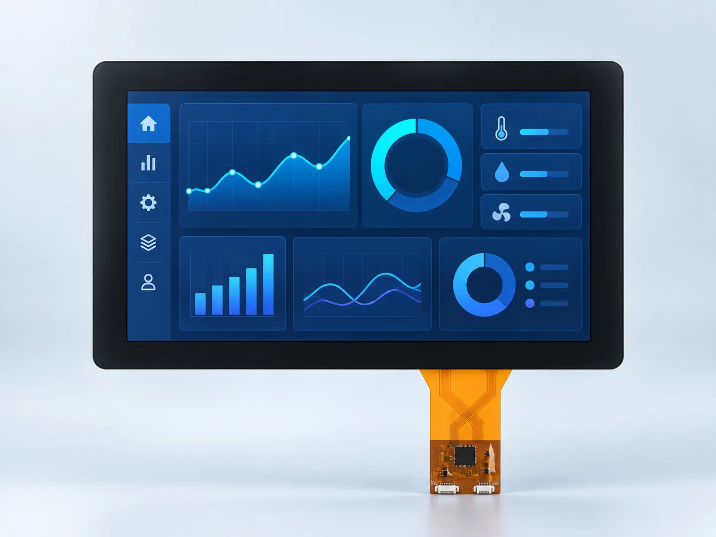
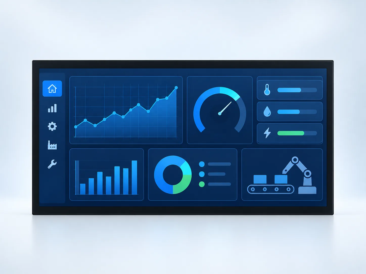
A PCAP module is not only a display with a touch sensor. The cover lens, touch controller, grounding, host communication, bonding and enclosure create one interactive stack that must be approved together.
Document bare-finger, glove, moisture, cleaning and gesture expectations. If a stylus is required, define the type and operating behavior instead of using “stylus support” as a generic request.
Provide the lens outline, thickness, material, edge treatment, printed border, viewing window and mounting concept. These inputs affect the sensor stack and the mechanical drawing.
Confirm the exact touch-controller part or approved alternative, communication path, supply, interrupt or reset requirements and software ownership from current documentation.
Identify nearby power converters, motors, radios, metal frames and display cables. Grounding and controller tuning must be validated in the finished equipment, not only on an open bench.
Decide whether the supplied configuration is air-gap or optically bonded and verify the exact materials and tolerances. Use the optical bonding review before freezing the stack.
Check sensor and lens outline, tail position, connector, adhesive zone, bezel pressure and assembly clearance. Route any required tail or pinout changes through a controlled FPC review.
It may be possible, but the result depends on the sensor, cover lens, controller capability, tuning, grounding, contamination and required glove type. Define the operating condition and validate it on the finished assembly.
No. Only rely on bonding when the exact product page and current documentation identify it. A PCAP sensor, a cover lens and optical bonding are separate configuration decisions.
These are engineering-review items. Send the lens drawing, viewing window, border artwork, thickness, edge requirements, mounting method and environment so feasibility can be reviewed without assuming a standard construction.
Verify touch response for intended users, controller communication, start-up and recovery, grounding and EMC behavior, display image quality, bonding or air-gap stack, enclosure pressure and the released mechanical drawing.
Use the engineering review to combine optical, mechanical and electrical requirements before sampling.