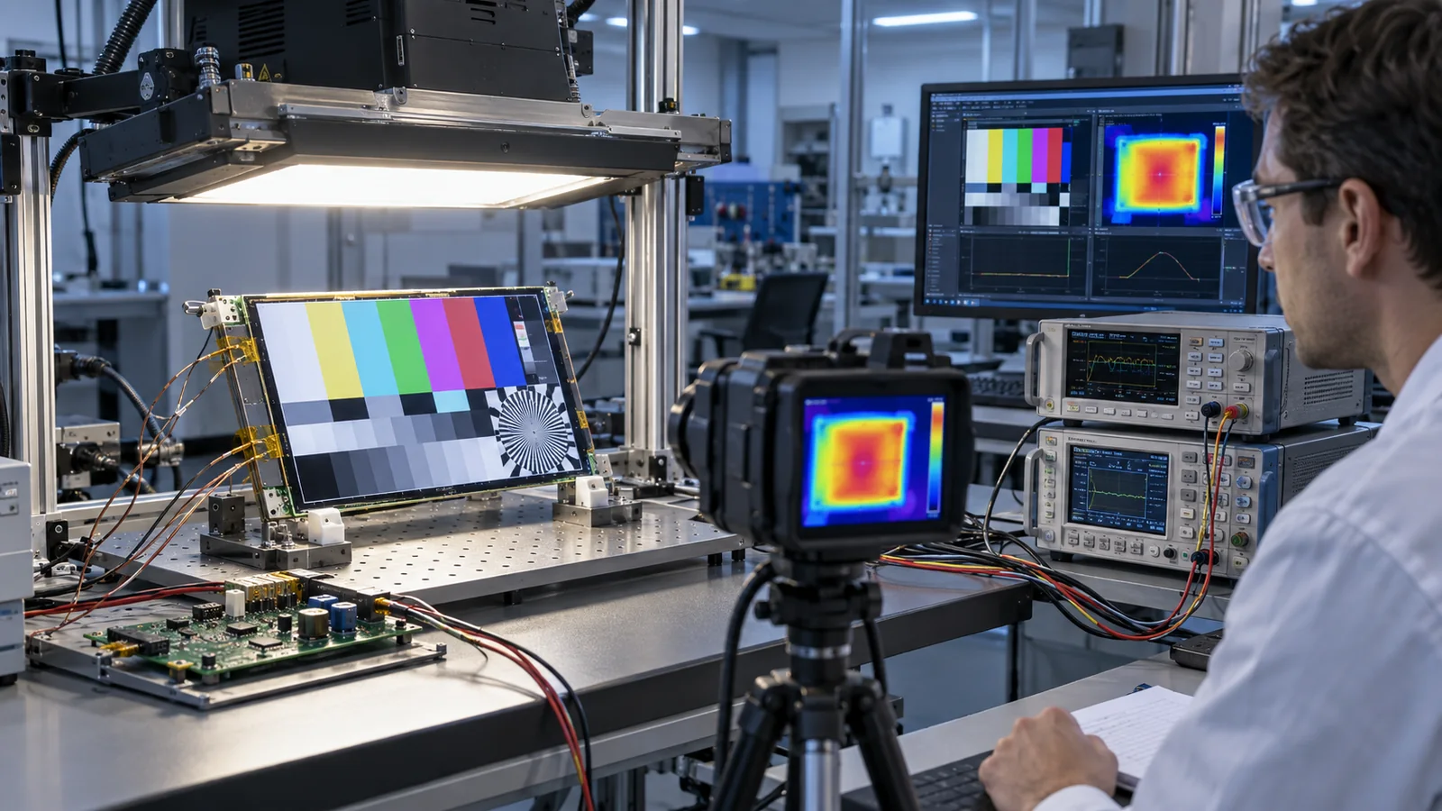
A display that reaches the target luminance on an open laboratory bench may behave very differently after installation behind cover glass in a sealed metal enclosure. The backlight shares its thermal environment with the LED driver, processor, power supply, touch controller and solar-heated front surface. As temperature rises, optical output, electrical efficiency, component margin and the allowed operating envelope can all change.
The correct design question is not “Can this TFT reach 1,000 nits?” It is “Can the completed equipment maintain the required readable luminance, image quality and component temperatures throughout the defined operating profile?”
The short answer
- Specify the minimum usable luminance at the finished display surface, not only the module’s nominal maximum.
- Calculate a first-pass backlight power budget, then measure the production-intent module and driver.
- Map the thermal path through the LED board, frame, PCB, enclosure and surrounding air.
- Add solar load and heat from other electronics; ambient temperature alone is not the complete condition.
- Use adaptive brightness or thermal foldback when the application permits, with explicit thresholds and UI behavior.
- Validate at worst-case voltage, image content, processor load, orientation and enclosure condition.
Where backlight power becomes heat
The LED backlight converts part of its electrical input into visible light. The remainder appears as heat in the LEDs and their electrical path. The driver also dissipates power through switching and conduction losses, and the display absorbs some light inside its polarizers, color filters, optical films and cover stack. In a sealed product, nearly all input power ultimately contributes to the equipment’s heat load, including light that is absorbed by nearby surfaces.
A first-order LED estimate is:
Driver input power is higher than delivered LED power by an amount determined by efficiency at the actual input voltage, load, switching conditions and temperature. Use this only for early budgeting; confirm with measured current, voltage and efficiency on the production-intent design.
The same luminance target can be reached with different LED counts, current densities, light-guide efficiencies and driver topologies. Therefore, nominal nits alone cannot predict temperature. Request the actual backlight electrical specification for the selected module revision.
Map the thermal path before selecting a solution
Heat flows through multiple paths: LED package to PCB, PCB to metal frame or spreader, frame to chassis, driver components to their board, and surfaces to internal air or the external environment. Each interface adds thermal resistance. Gaps, small contact areas, insulating tapes, adhesive thickness and a plastic bezel may dominate a path that looked efficient in a simplified CAD model.
For one defined path, a basic steady-state estimate uses:
This relationship is useful for comparing design directions, but a TFT assembly has several parallel heat paths, distributed sources and transient behavior. Define the start and end points of every thermal-resistance value and verify the result experimentally.
LED junction temperature is especially important but often cannot be measured directly in a finished backlight. Suppliers may specify a solder-point or board-temperature location and a package thermal-resistance method. Place sensors at defined points, document attachment and emissivity assumptions, and avoid treating internal-air temperature as junction temperature.
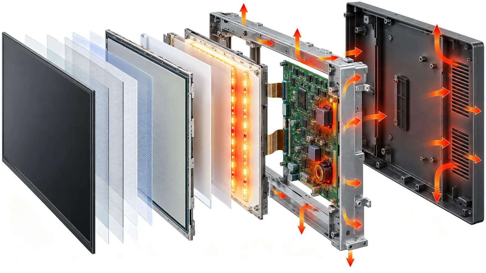
What adds to the thermal burden?
| Contributor | Why it matters | What to verify |
|---|---|---|
| LED current and count | Set electrical power, current density and source distribution. | Current per string, current balance, peak/PWM behavior and rated operating region. |
| Backlight driver | Switching losses create local hot spots and efficiency changes with operating point. | Input range, efficiency, IC/MOSFET/diode/inductor temperatures, derating and protection. |
| Optical transmission | Touch layers, cover glass, polarizers, coatings and adhesives affect how much emitted light reaches the viewer. | Finished-stack luminance and contrast, not only bare-module luminance. |
| Solar absorption | Direct sun can heat the cover, black mask, LCD and enclosure even before the backlight is considered. | Worst-case sun angle, surface colors, soak duration and internal temperature rise. |
| Nearby electronics | Processors, power converters and radios may share the same sealed air volume or chassis path. | Maximum system load and simultaneous operation, not an idle display-only test. |
| Mechanical stack | Frames, seals, tapes and gaps can spread heat or block an intended path. | Production materials, contact pressure, flatness, tolerances and assembly consistency. |
| Orientation and airflow | Natural convection and surface temperatures change with installation. | Actual portrait/landscape angle, vents, filters, fan state and wall or panel mounting. |
How excessive temperature can affect the display system
LED output and maintenance
LED optical behavior and long-term maintenance depend on operating current and temperature. Higher junction temperature can reduce efficacy and available light output while increasing reliability stress. Do not apply a generic “every 10°C” lifetime rule to an unknown backlight. Use the LED or module supplier’s data and the defined measurement point.
For a deeper specification review, see Industrial TFT LCD Backlight Lifetime: What Engineers Should Verify.
Driver and power components
The driver IC, switching device, diode, inductor and capacitors can operate at very different temperatures even when board ambient appears acceptable. Check datasheet operating limits and component derating at worst-case input voltage and LED load. Confirm that open-string, short-string, overvoltage and overtemperature responses do not create unsafe repetitive cycling or an unusable display state.
LCD, optical films, adhesives and touch stack
The LCD cell, polarizers, light-guide materials, reflector, diffusers, bonding materials and cover stack each have their own temperature and environmental limits. Heat, UV, humidity and mechanical stress can interact. Potential concerns include image-quality change, optical drift, adhesive stress, bubbles or delamination, but the relevant mechanisms and limits must be verified for the exact materials and construction.
Enclosure and user-accessible surfaces
A display can remain electrically functional while the front cover, bezel or rear enclosure becomes unacceptable for user contact or surrounding components. Include surface-temperature and regulatory requirements in the equipment-level review. A sealed outdoor enclosure also needs a defined way to reject heat without undermining ingress protection.
Reduce the required brightness before adding power
Outdoor readability depends on emitted luminance relative to reflected ambient light. Increasing the backlight attacks only one side of that relationship. Before increasing LED power:
- Measure the real illumination and viewing geometry.
- Reduce dominant surface and internal reflections where the project allows.
- Use high-contrast UI colors, legible fonts and suitable icon sizes.
- Control the cover black mask, air gaps and optical interfaces.
- Evaluate anti-glare, anti-reflective and optical-bonding options as distinct tools.
The sunlight-readable TFT guide explains the full ambient-contrast problem. Optical improvement does not guarantee that a lower backlight will meet the requirement, but it can prevent unnecessary electrical and thermal margin from becoming the default solution.
Use brightness control as a thermal tool
Many industrial displays do not need peak output continuously. An ambient-light sensor can raise brightness in strong light and reduce it indoors or at night. A temperature sensor can support thermal foldback before component limits are exceeded. Effective control needs more than a sensor and a linear dimming command:
- Define the sensor location and what temperature it represents.
- Set separate warning, foldback and shutdown thresholds where appropriate.
- Add hysteresis and filtering to prevent visible brightness hunting.
- Preserve legibility of alarms and safety-critical information during foldback.
- Record faults and temperature events for field diagnosis.
- Define recovery behavior after cooling or a power cycle.
PWM dimming and analog dimming affect the LEDs and driver differently. Verify dimming ratio, minimum pulse width, flicker, camera compatibility, color behavior, audible noise and peak current across temperature. A control algorithm should stay inside the validated backlight operating area.
Practical thermal design actions
- Choose an efficient operating point. Compare output and power at the required finished-stack luminance, not only at maximum current.
- Spread heat without loading the glass. Use the module frame, PCB copper or a designed spreader while respecting flatness, mounting and mechanical-stress limits.
- Give the driver a real thermal path. Place power components and copper for heat flow, then evaluate them inside the actual enclosure.
- Separate heat sources where possible. Avoid placing the LED driver beside a processor or power converter if both create the same local hot spot.
- Control thermal interfaces. Define pad or adhesive material, thickness, compression, contact area and assembly tolerance.
- Plan for solar load. Consider cover absorption, dark borders, coatings, enclosure color and the time required to reach a hot steady state.
- Add graceful control. Use ambient brightness scheduling and temperature-based foldback where the application permits.
- Keep service and change control in scope. A substituted LED, driver component, optical film or adhesive can change both output and temperature.
High-brightness thermal validation checklist
Test the completed display subsystem in a production-intent enclosure. A useful matrix includes maximum and minimum input voltage, low and high ambient, peak backlight command, realistic UI patterns, maximum processor load, expected orientation, sealed or filtered airflow states and direct solar loading where relevant.
Measure at least:
- Finished-display luminance and uniformity after stabilization.
- Backlight voltage, string current, input power and driver efficiency.
- Supplier-defined LED-board or solder-point temperature.
- Driver IC, switching device, diode, inductor and critical capacitor temperatures.
- LCD surface, cover, black-mask, bezel and user-accessible enclosure temperatures.
- Internal and external ambient temperature at defined locations.
- Foldback threshold, response time, hysteresis, minimum luminance and recovery.
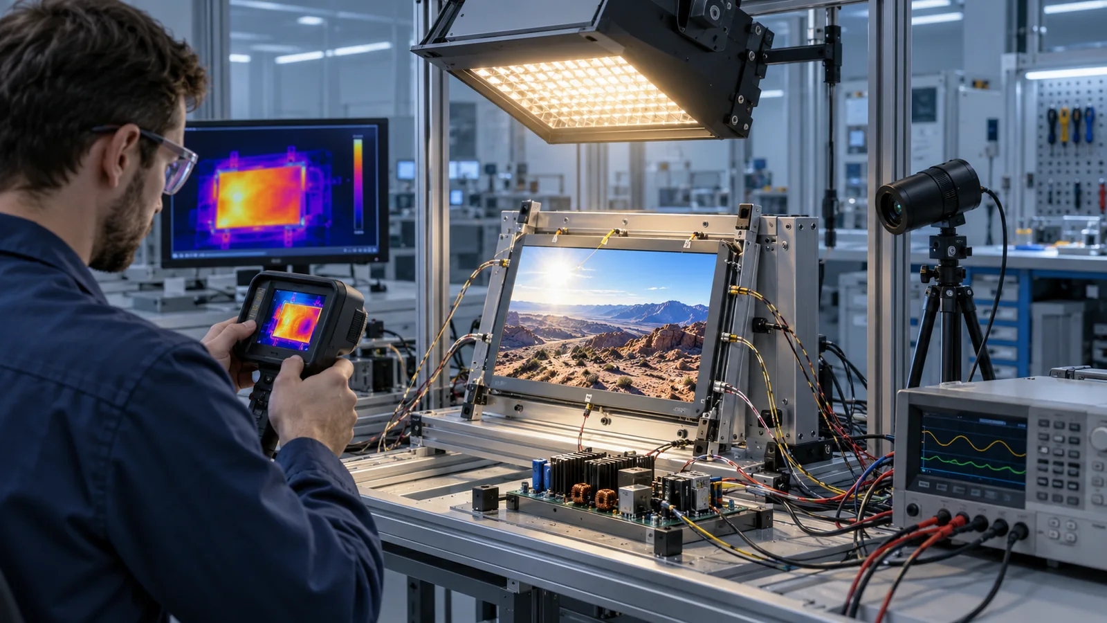
Run long enough to identify the hot steady state and also inspect transient peaks during startup, brightness transitions and changing processor load. Repeat critical measurements across representative units and assembly tolerances. Thermal-camera images are excellent for finding hot spots, but confirm emissivity-sensitive areas with appropriate contact sensors or calibrated methods.
Selecting a module without over-specifying
Use the 800 vs 1000 vs 1200 nit comparison to translate the application’s light environment into an initial luminance range. Then compare interface, operating temperature, mechanics, touch and supply requirements. Current catalog examples include the 5-inch DS-T050BWSWA-02, 7-inch DS-T070SWHWA-01 and 10.1-inch DS-T101HIEWA-01. Their catalog pages are starting points; confirm the current drawing, backlight electrical specification and application-level thermal behavior before release.
Browse the complete high-brightness TFT selection path or combine brightness and temperature filters in the industrial TFT catalog.
Common thermal-design mistakes
- Selecting by maximum luminance without defining the real readability condition.
- Using LED input power as the only heat source in a sealed enclosure.
- Validating an open module on a bench but shipping it behind a cover in a closed housing.
- Measuring room ambient while leaving LED-board, driver and cover temperatures undefined.
- Assuming a generic temperature-to-lifetime rule applies to every LED and assembly.
- Adding optical layers without remeasuring finished-stack transmission and thermal behavior.
- Using thermal foldback without specifying minimum readable brightness and recovery behavior.
- Ignoring production changes to LEDs, films, adhesives or power components.
What to send for a thermal design review
- Display size, resolution, interface, target and minimum acceptable luminance.
- Ambient illumination, sun exposure, viewing angle and UI content.
- Touch, cover glass, coating, optical bonding and black-mask stack.
- Input-voltage range, dimming method, brightness profile and daily duty cycle.
- Operating ambient range, enclosure material, sealing, airflow and orientation.
- Nearby heat sources and maximum simultaneous equipment power.
- Temperature limits, sensor locations, foldback behavior and acceptance criteria.
- Expected service life and qualification or change-control requirements.
These items fit naturally into the industrial TFT LCD requirements checklist. Sending them together reduces the risk of solving brightness, optics, thermal design and backlight reliability in separate late-stage revisions.
Related engineering guides
Technical references
- ams OSRAM — Reliability and Lifetime of LEDs: current, temperature, efficiency, thermal design and reliability relationships for LEDs.
- ams OSRAM — Package-Related Thermal Resistance of LEDs: thermal-resistance definitions, junction-temperature relevance and temperature-measurement considerations.
- Texas Instruments — Temperature Sensing in Automotive and Industrial Displays: panel and backlight monitoring, brightness regulation, throttling and shutdown context.
- Texas Instruments — LED Thermal Foldback with NTC Thermistor: an implementation example for reducing LED current as measured temperature rises.
- Texas Instruments — Automotive LCD Backlight Reference Design: ambient-light brightness control, temperature monitoring and protection functions.