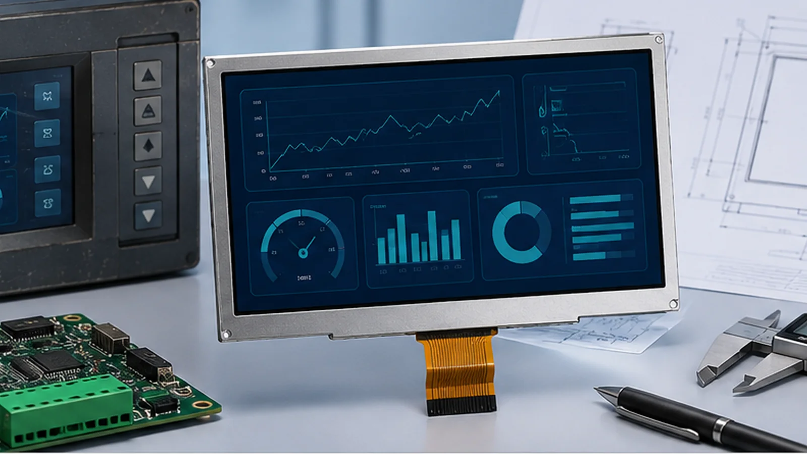
An obsolete display can stop production long before the rest of the equipment reaches end of life. The replacement goal is usually clear: preserve the enclosure, host PCB, software and certification evidence as far as practical. Achieving that goal requires a controlled interface comparison, not a search for the same diagonal and resolution. The industrial TFT LCD selection guide provides a companion seven-point shortlist.
What “drop-in replacement” should mean
A true drop-in replacement fits the mechanical envelope, mates with the existing connector, uses the same pin functions and electrical levels, accepts compatible video timing and power sequencing, meets the optical requirement and behaves correctly across the application temperature range. If one of these conditions changes, the solution may still be a good replacement—but the change and validation work must be explicit.
Use three classifications during sourcing:
- Direct replacement: no intended host or enclosure change after documented comparison.
- Adapted replacement: controlled FPC, adapter, bracket, firmware or optical-stack change.
- Redesign candidate: multiple core interfaces change, so a broader system redesign is more honest and safer.
1. Compare mechanical drawings dimension by dimension
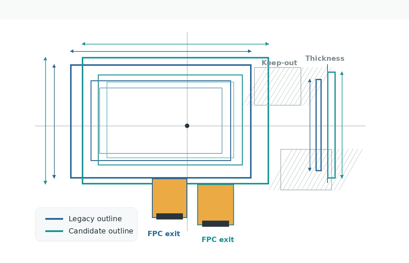
Overlay the legacy and candidate drawings from a shared datum. Compare overall width, height and thickness; active area and viewing area; pixel orientation; bezel position; glass and metal-frame features; mounting tabs; connector position; FPC exit and bend direction; component keep-out areas; and touch/cover-lens outline.
Do not compare nominal values only. Include tolerances and the enclosure stack: adhesive, gasket compression, bezel overlap, cover glass, chassis flatness and allowed pressure on the module. A 0.5 mm shift can matter if it moves the active area behind printed ink or forces the FPC into a sharp bend.
2. Treat the FPC and pinout as separate checks
Matching the connector pitch and pin count does not prove electrical compatibility. Confirm contact side, insertion direction, pin 1, tail thickness, stiffener length and exposed-contact dimensions. Then compare every pin function: logic supply, analog supply, grounds, RGB data or differential pairs, pixel clock, synchronization, data enable, reset, serial control, backlight anode/cathode and no-connect pins.
Look for dangerous substitutions such as a supply pin where the legacy part had ground, different backlight polarity, a reset pin with a different active state or a changed logic-voltage domain. If the module is close but the tail is not, the custom TFT LCD FPC and pinout workflow may preserve the host connector—but it must be reviewed as an electrical design, not a cosmetic reroute.
3. Compare interface timing and data mapping
Resolution and interface family are only the first line of the comparison. For parallel RGB, check pixel-clock range and edge, horizontal and vertical sync polarity, data-enable mode, porch values, color bit order and input voltage. For LVDS, check single/dual channel, clock, pair assignment and data mapping. For MIPI DSI, check lane count, mode, commands and initialization sequence. For MCU interfaces, check command set, bus width and write-cycle timing.
A candidate may light up on the bench yet show intermittent lines, shifted pixels, color errors or temperature-sensitive behavior if the timing margin is narrow. Confirm the host can generate timing within the candidate’s allowed ranges, then test at voltage and temperature corners.
4. Verify power, backlight and start-up sequence
Compare all supply rails, current requirements, reset timing and power-on/off sequence. The LCD logic and backlight are separate loads. Check LED string voltage, current, number of strings, dimming method and connector pins. A new backlight may exceed the existing driver’s voltage or thermal capability even when the display interface is compatible.
Observe shutdown behavior too. Incorrect rail order or leaving signals driven into an unpowered module can create image artifacts or stress. Use the current datasheets and host schematic to define the sequence before sample testing.
5. Match optical performance in the complete product
Compare luminance, contrast, viewing direction or IPS behavior, color characteristics, polarizer orientation and response at temperature. If the product uses touch or cover glass, check whether the legacy unit was air bonded or optically bonded and whether it used AG, AR or other surface treatment.
A brighter candidate can still look worse behind a reflective front stack. A different polarizer can create a dark view through polarized sunglasses. A different active-area placement can expose the printed border. Use the actual UI and final lens in the approval test.
6. Requalify environment and materials
Operating and storage temperature must each meet the equipment requirement. Confirm cold start, pixel response, backlight start-up, touch behavior, adhesive, gasket and cover-lens performance. If the original design relied on undocumented margin outside its rating, do not carry that assumption into the replacement.
Also review shock, vibration, humidity, condensation, ESD and cleaning requirements relevant to the product. The replacement assessment should align with the equipment’s existing qualification plan and any regulatory change-control obligations.
Replacement comparison matrix
| Area | Legacy evidence | Candidate evidence | Approval question |
|---|---|---|---|
| Mechanical | Approved drawing and installed photos | Controlled drawing and samples | Does the tolerance stack fit without pressure or occlusion? |
| FPC/connector | Tail drawing and connector part | Tail drawing and mating data | Do contact side, pin 1, pitch and insertion agree? |
| Pinout | Datasheet and host schematic | Current pin definition | Are every supply, ground and signal function compatible? |
| Timing | Host settings or measured waveform | Allowed timing table | Is there margin across voltage and temperature? |
| Backlight | Driver voltage/current and dimming | LED electrical data | Can the existing driver power it safely? |
| Optical/touch | Acceptance criteria and front stack | Optical data and touch configuration | Is the real assembled product readable and operable? |
| Environment | Equipment qualification limits | Module ratings and samples | Does it pass the required corner conditions? |
7. Use samples to close risks, not to discover basic incompatibility
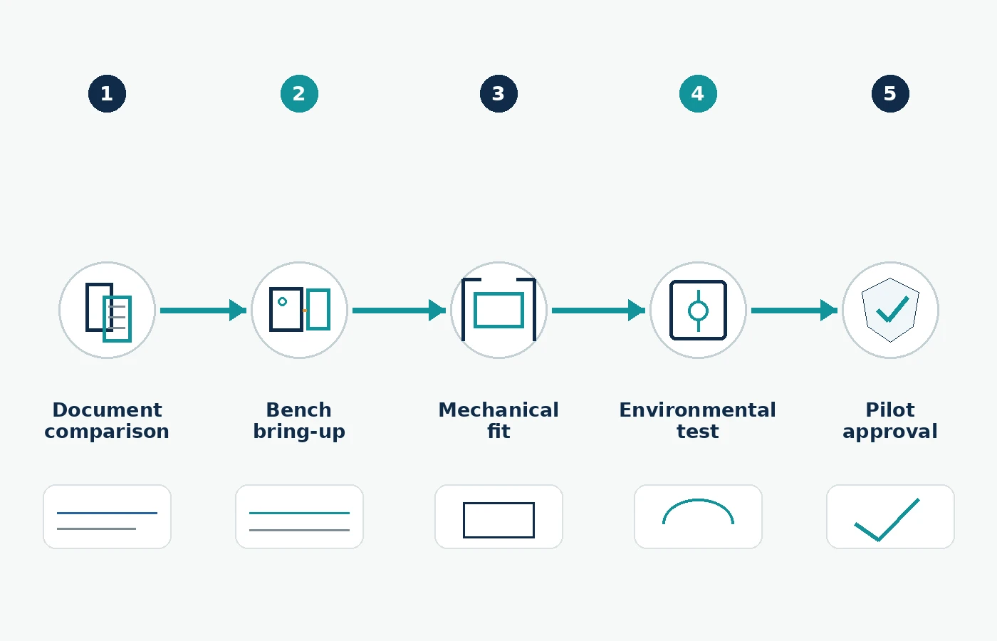
Drawing and datasheet comparison should eliminate obvious mismatches before samples are ordered. The sample phase then verifies the remaining system behavior.
Check rails, current, reset, interface timing, color mapping, orientation, backlight and touch communication.
Install in the real enclosure and inspect alignment, gasket load, FPC bend, connector strain and thermal clearances.
Run the real UI, dimming, sleep/wake, power cycles, ESD-relevant use and touch modes.
Use the project’s cold-start, hot operation, humidity, vibration and other required profiles.
Freeze the exact model, drawing revision, configuration, acceptance criteria and incoming inspection plan.
What to send TFTWorks for a replacement review
Send the obsolete model number and datasheet if available, plus the mechanical drawing, pinout, interface timing, backlight data and photos. Add the host processor or controller, available supply rails, target brightness, touch requirement, operating/storage temperature and annual quantity context. If information is missing, identify it as unknown rather than estimating.
Browse the current industrial TFT module shortlist or use the engineering customization path when the closest standard module needs an FPC, interface, touch or cover-glass adaptation.