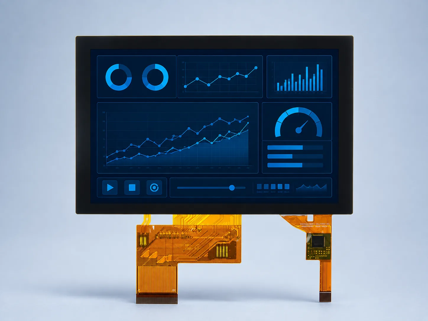
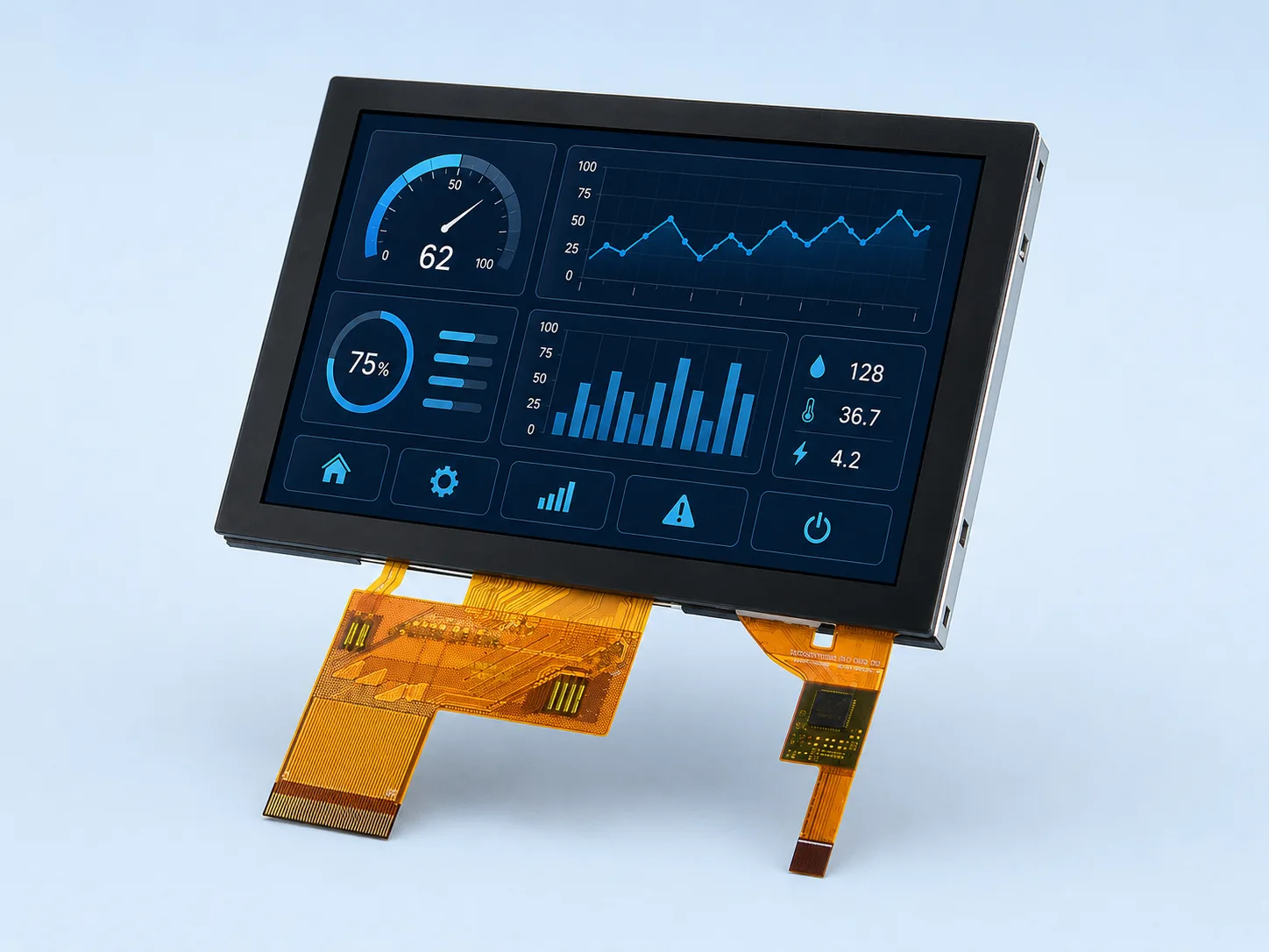
Front view
Display and touch FPC routes are fully visible.
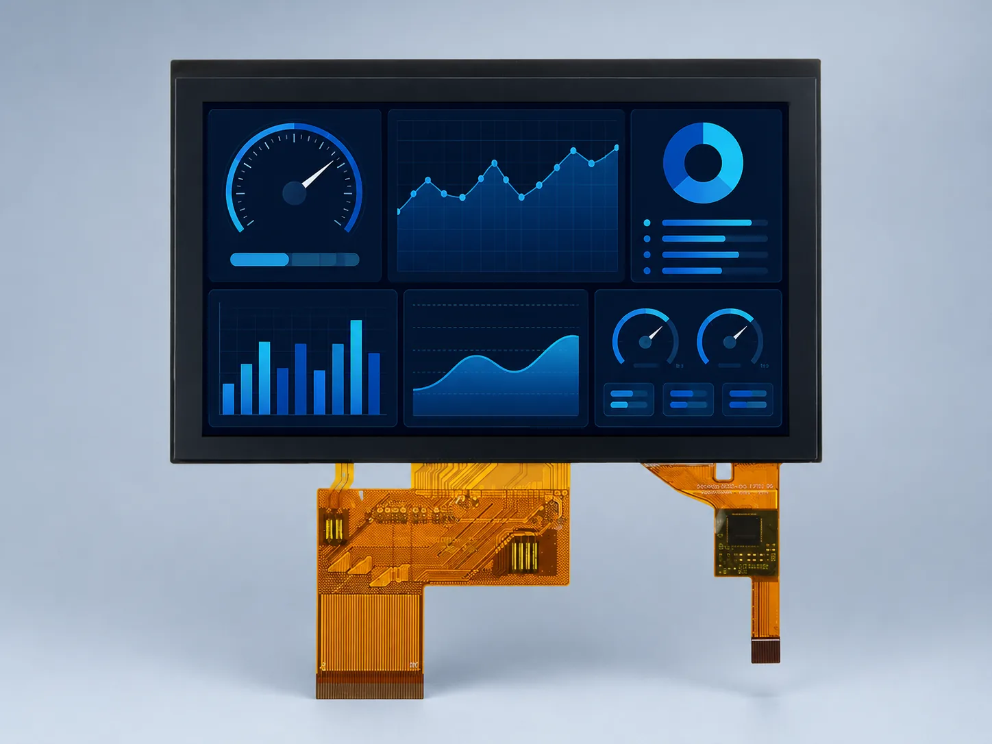
DS-T050BWSA-02CP combines a 5 inch 800×480 IPS panel, 900 cd/m² luminance, PCAP touch and optical bonding for industrial HMI integration.
Confirm the current datasheet, pinout and mechanical drawing before design-in.
| Item | DS-T050BWSA-02CP |
|---|---|
| Diagonal size | 5.0 inch |
| Resolution | 800×480 |
| LCD type | IPS |
| Luminance | 900 cd/m² |
| Module interface | RGB 24-bit, 40-pin |
| LCD driver IC | ST7265 |
| Touch panel | CTP / PCAP |
| Touch controller | ST1633i |
| Bonding type | Optical bonding |
| Active area (W×H) | 108.00×64.80 mm |
| Module outline (W×H×D) | 123.26×80.06×4.30 mm |
| Operating temperature | −20 to 70 °C |
| Storage temperature | −30 to 80 °C |
Display and touch FPC routes are fully visible.
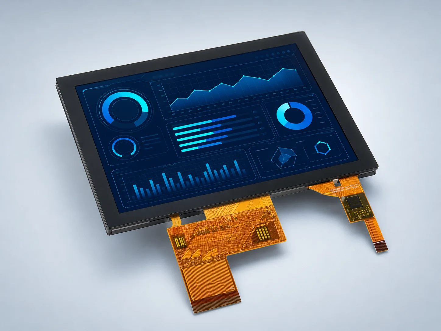
Visual reference only; use the mechanical drawing for dimensions.
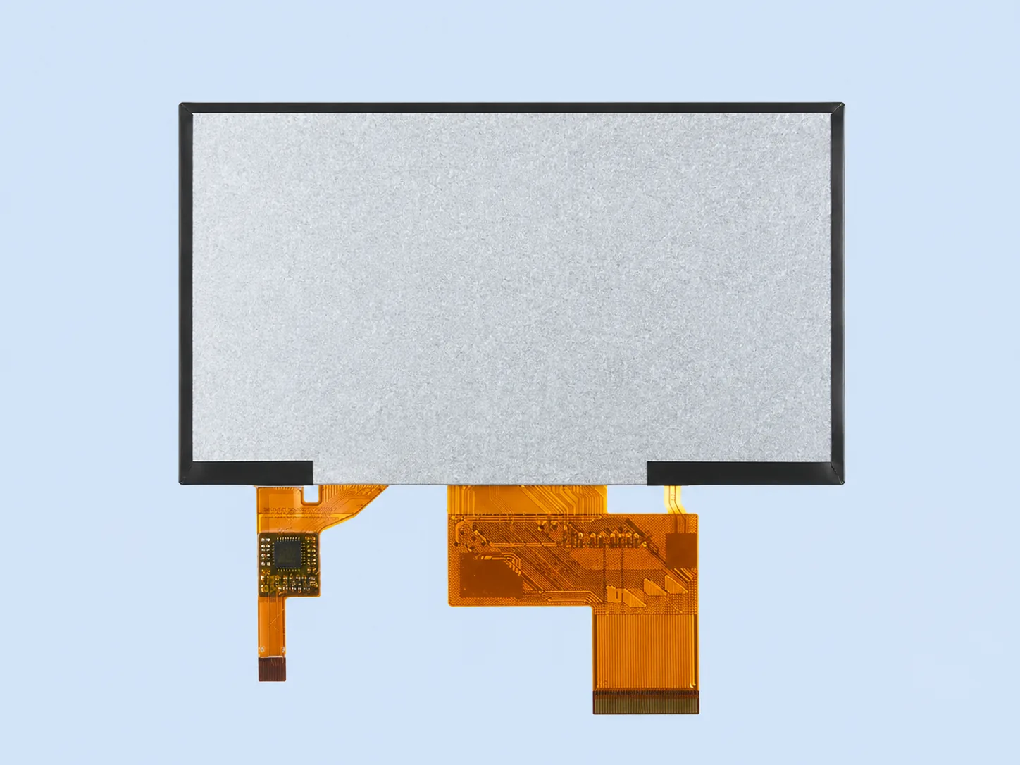
Backplate and complete FPC routing reference.
The touch-controller tail and display FPC are shown for visual orientation. Verify the approved drawing, pinout and keep-out zones before tooling.
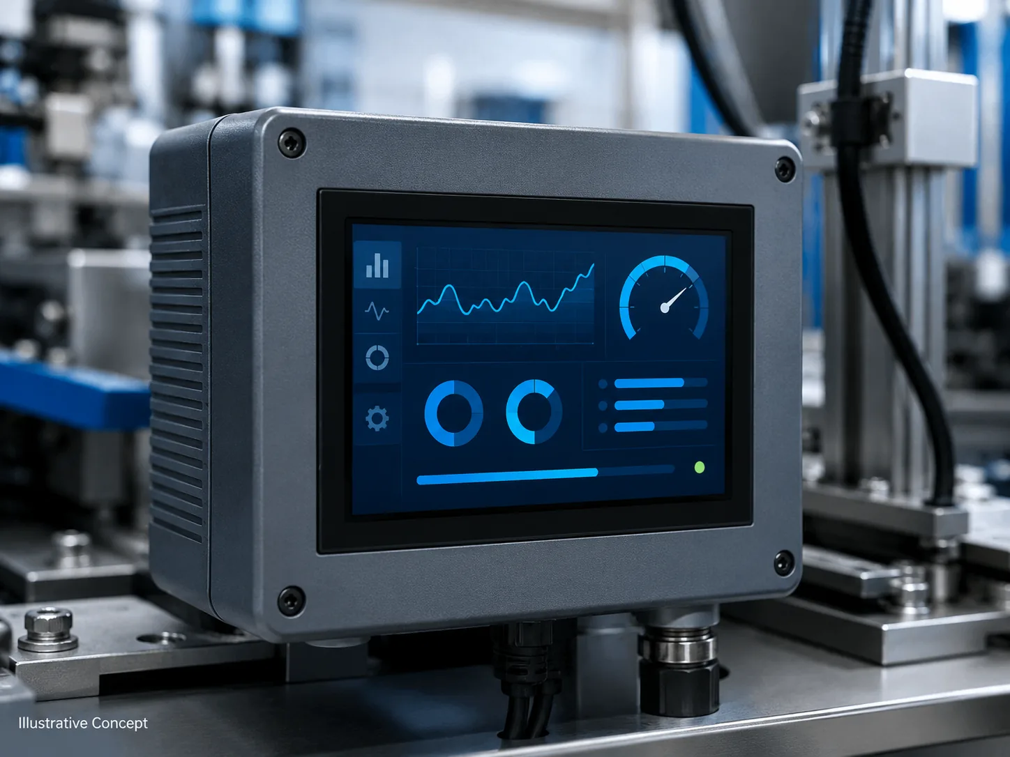
Illustrative industrial HMI concept only; it is not a documented customer deployment or mechanical integration drawing.
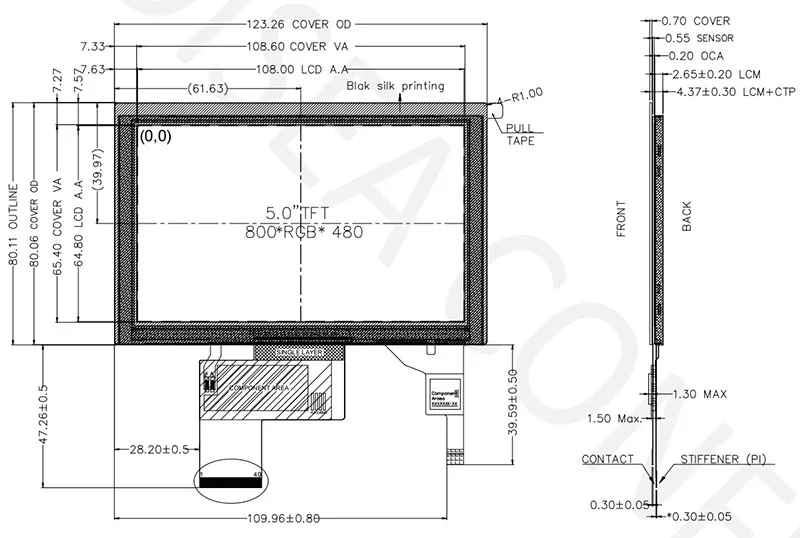
Use the current approved drawing for production release, tolerances and keep-out zones.
This configuration combines a 5-inch 800×480 IPS TFT LCD, 900 cd/m² luminance, PCAP touch and optical bonding. Approve the display, ST1633i touch controller, RGB interface, bonded stack and enclosure as one system rather than treating the touch panel as a separate accessory.
The display uses RGB 24-bit, 40-pin while the PCAP function has its own controller requirements. Confirm the display timing and the ST1633i communication, power, reset and software path from the current documentation.
Use the verified 123.26×80.06×4.30 mm module outline and approved drawing for the enclosure review. Check viewing window, bezel clearance, FPC routes, connector access and assembly pressure.
Optical bonding is documented for this configuration, but finished readability still depends on ambient light, cover surface, UI contrast and installation angle. Use the optical bonding design review to define the sample test.
Yes. Optical bonding is part of the verified configuration described on this page.
The verified touch controller is ST1633i. Confirm communication, supply, reset and firmware requirements against the current documentation for the sample.
Do not assume so. The PCAP bonded configuration has a different complete-module outline and touch-related electrical and mechanical requirements. Compare both current drawings and connector definitions.
Verify display image and timing, touch response for the intended user and environment, controller communication, grounding and EMC behavior, bonded-stack appearance, enclosure pressure and complete FPC routing.
Send the host platform, enclosure constraints, target quantity, touch environment and viewing conditions for a fit review.