Custom TFT LCD Engineering for Optical, Electrical and Mechanical Fit
Define controlled changes around the host system and enclosure: backlight, FPC and pinout, touch, cover glass, bonding, interface and driver-board integration.
Start with a verified base module and a controlled requirement
A custom TFT LCD project should separate fixed panel characteristics from the parts that can be engineered around them. Bring the target drawing, host interface, environment and annual demand into the first review.
Round and bar-type TFT LCD projects need early review of active area, outline, FPC exit, interface and touch stack. Availability and specifications must be confirmed against the exact model and current datasheet.
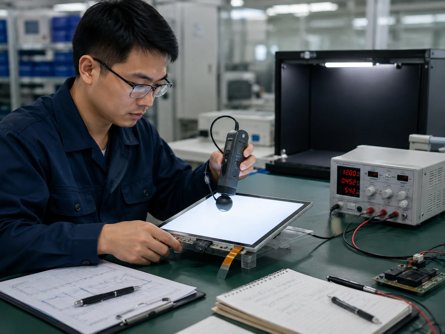
Brightness & Backlight
Define optical target, power, lifetime and environment.
Compare outdoor luminance →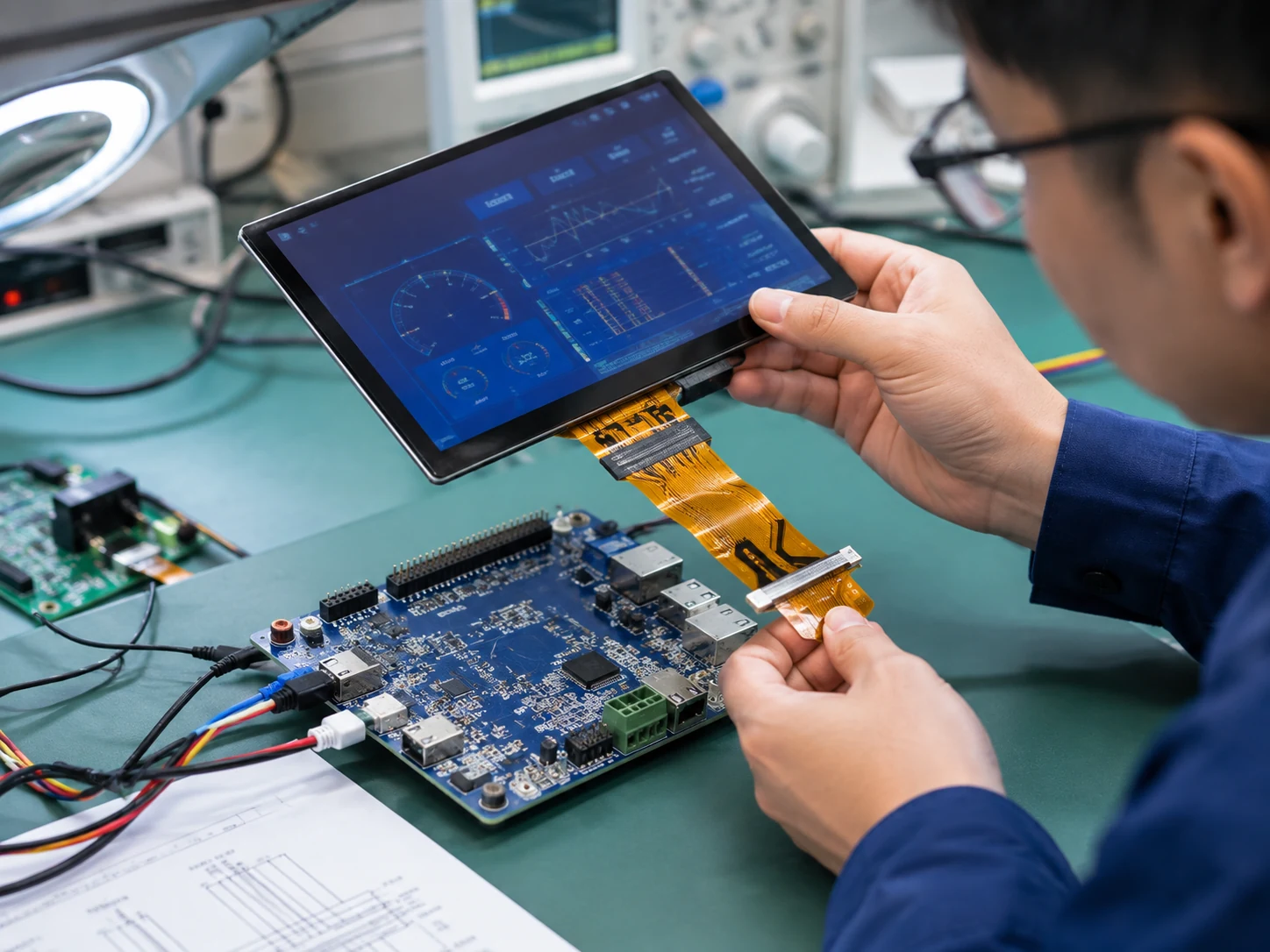
Custom FPC & Interface
Adapt routing, pinout, connector and host-side integration.
Review FPC requirements →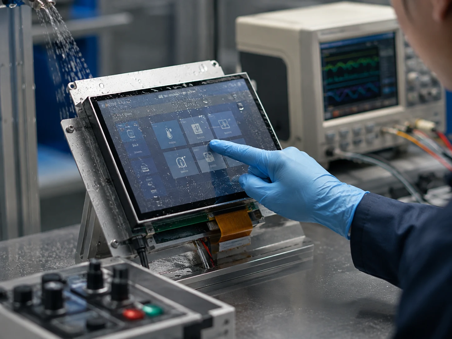
Touch Integration
PCAP or RTP, controller, glove and water requirements, and tuning.
Compare touch options →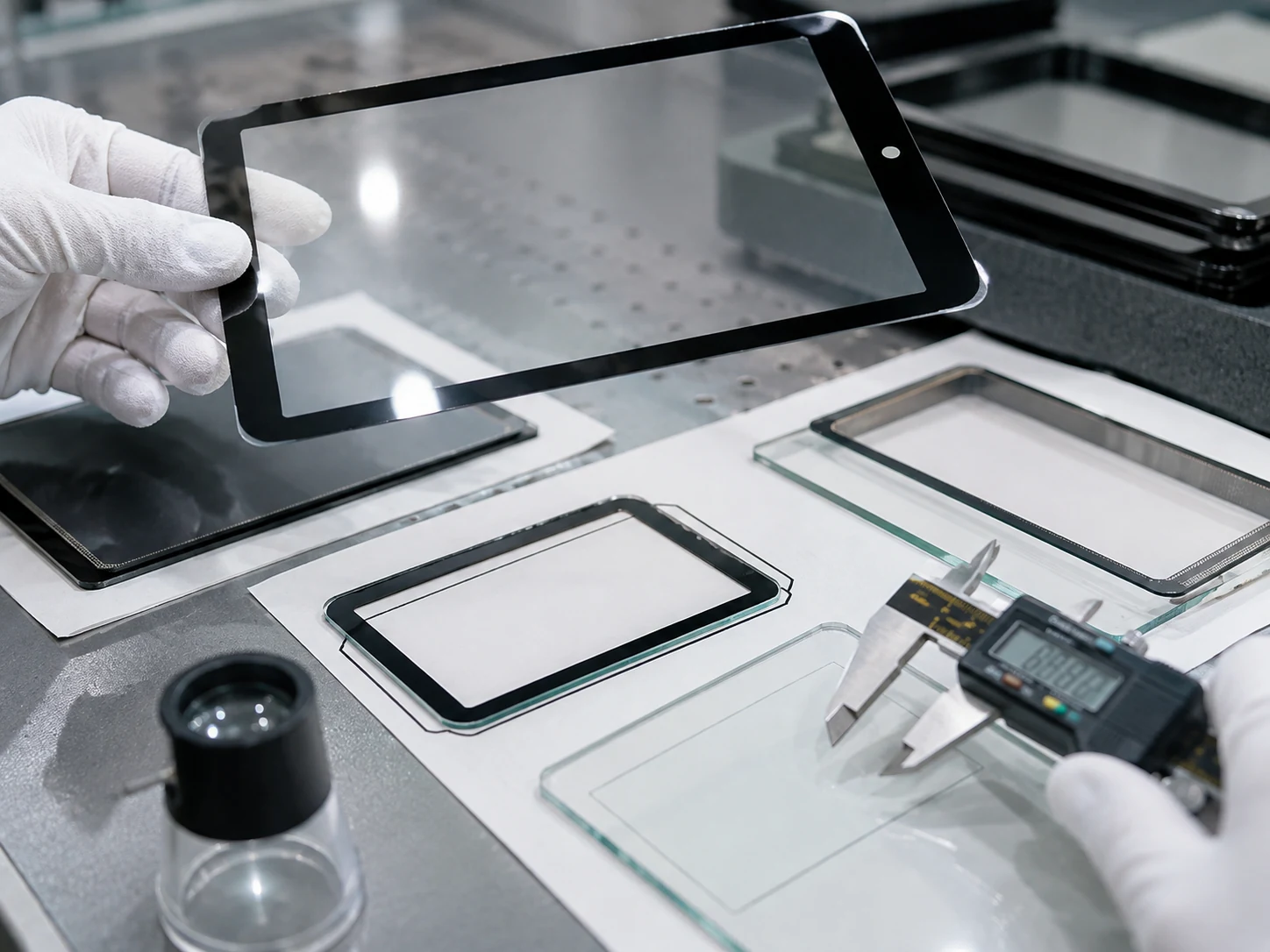
Cover Glass
Outline, thickness, printing, surface finish and mechanical fit.
Compare AG, AR and bonding →
Optical Bonding
Review readability, reflections and front-stack robustness.
Read the bonding design guide →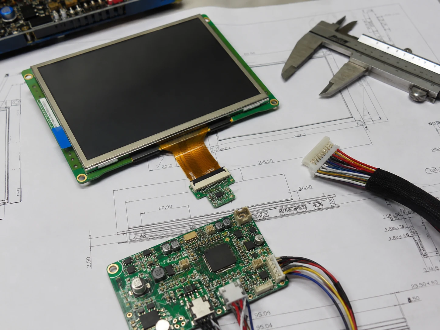
Driver Board
Evaluate controller and adapter needs for the target host system.
Read the controller-board guide →What happens before a customized sample
A B2B buyer needs to know what information is required, what is reviewed and where risk is closed.
What should be controlled in a custom TFT LCD project?
A useful engineering request connects every proposed change to a measurable input and an approval document. This keeps the display, touch stack, host electronics and enclosure on the same revision.
| Review area | Input to provide | Evidence to approve |
|---|---|---|
| Optical and backlight | Ambient light, viewing angle, luminance target, duty cycle, power and heat limits | Defined test condition, optical target and representative assembled-sample result |
| FPC and electrical | Host output, pin mapping, voltage rails, connector, contact direction and cable route | Current pinout, timing document, controlled FPC drawing and bring-up result |
| Touch and cover lens | Finger, glove or stylus input; water exposure; lens outline, thickness, printing and surface treatment | Touch drawing, controller configuration, mechanical drawing and use-condition test |
| Mechanical integration | Enclosure opening, stack height, mounting, keep-outs, bend radius and assembly sequence | Approved module or assembly drawing with agreed tolerances |
| Supply and quality | Sample quantity, forecast, lifecycle expectation and required validation evidence | Locked configuration, sample approval record and production change-control plan |
A feasibility review is model-specific. A requested change should not be treated as available until the exact base module, configuration and current documentation are confirmed.
Prepare the interface and FPC review
RGB, LVDS, MIPI DSI or MCU?
Compare host output, timing, distance, pin count and software requirements.
Read the interface guide →LVDS integrationSelect and validate the LVDS cable length
Review the complete source, cable, connector and display link before freezing the harness.
Read the LVDS cable guide →RGB integrationConfigure pixel clock, sync and porches
Calculate RGB timing and avoid common polarity, mapping and bandwidth risks.
Read the RGB timing guide →FPC customizationReview pinout, connector and FPC geometry
Define the electrical mapping and controlled drawing before sample approval.
Read the FPC guide →Custom TFT LCD engineering FAQ
What information is needed to review a custom TFT LCD?
Provide the application, required size and resolution, host interface, mechanical drawing or envelope, ambient light, operating and storage temperatures, touch method, front-stack requirements, target quantity and lifecycle expectations.
Can a TFT LCD FPC or pinout be changed without reviewing the host?
No. The source mapping, voltage rails, control signals, connector, contact direction, FPC geometry and timing documentation should be reviewed together. Use the custom FPC guide to prepare the electrical and mechanical inputs.
Is optical bonding the same as adding a touch panel?
No. Touch technology, cover glass and optical bonding are separate decisions. Define the complete stack, then validate optics, mechanics, environment and touch performance. Compare the PCAP selection path with the optical bonding design review.
What should be approved before a custom display enters production?
Approve the exact sample configuration, current datasheets, controlled drawings, pinout, interface timing, cosmetic criteria and the project-specific validation plan. The approved configuration—not a generic family description—should become the production reference.
Already have a drawing or reference display?
Attach it with your target changes so the review starts from facts rather than a generic inquiry.