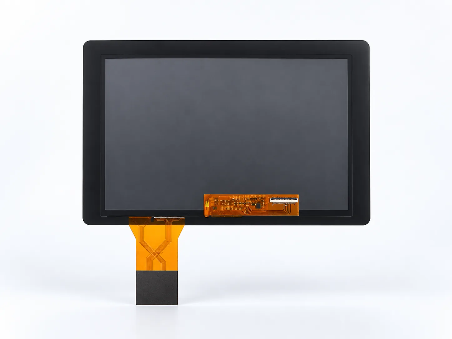
Front assembly reference
Black PCAP cover glass and both FPC assemblies are visible.
DS-T101HIEWA-01CP combines a 10.1-inch 1280×800 IPS panel, 850 cd/m² luminance, PCAP touch and optical bonding for industrial HMI integration.
Confirm the current datasheet, pinout and approved mechanical drawing before design-in.
| Item | DS-T101HIEWA-01CP |
|---|---|
| Diagonal size | 10.1 inch |
| Resolution | 1280×800 |
| LCD type | IPS |
| Luminance | 850 cd/m² |
| Module interface | LVDS 6/8-bit, 40-pin |
| LCD driver IC | EK79202 |
| Touch panel | CTP / PCAP |
| Touch controller | ILI2511 |
| Bonding type | Optical bonding |
| Active area (W×H) | 216.96×135.60 mm |
| Module outline (W×H×D) | 260.00×170.00×6.95 mm |
| Operating temperature | −30 to 85 °C |
| Storage temperature | −30 to 85 °C |
Black PCAP cover glass and both FPC assemblies are visible.
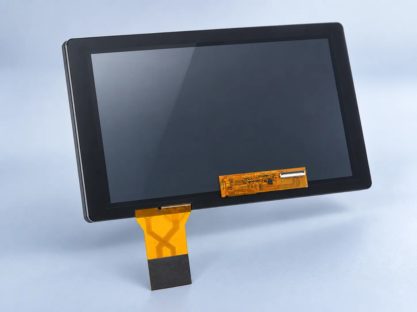
Use the approved drawing for mounting, connector routing and tolerances.
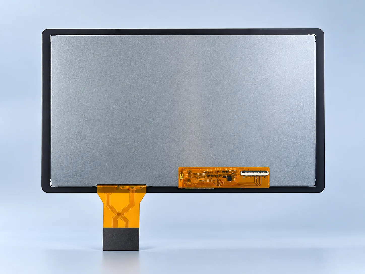
Use current approved mechanical and electrical documentation for design details.
The touch FPC and LCD interface assembly are shown for visual orientation. Verify the approved drawing, pinout and keep-out zones before tooling.
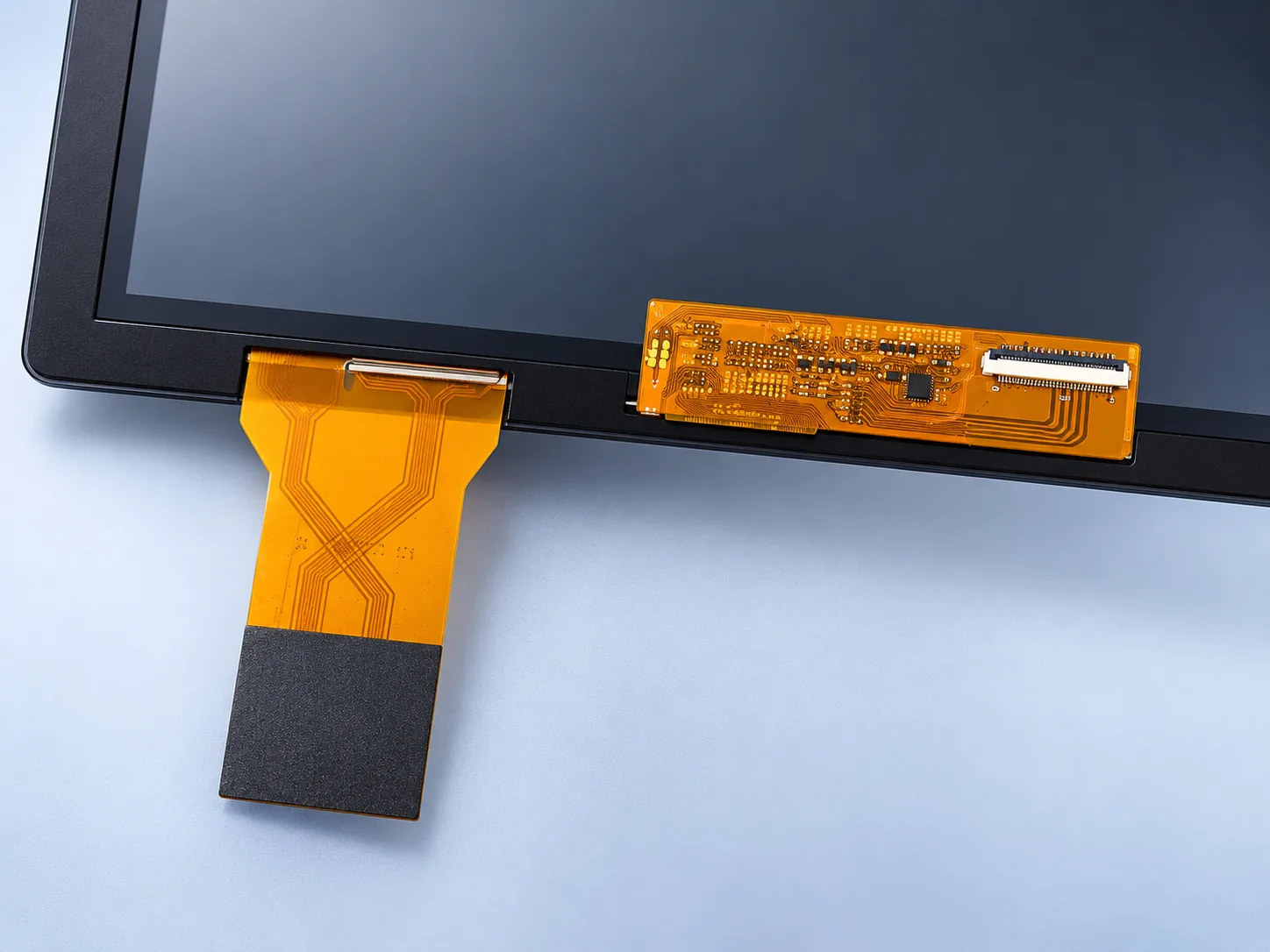
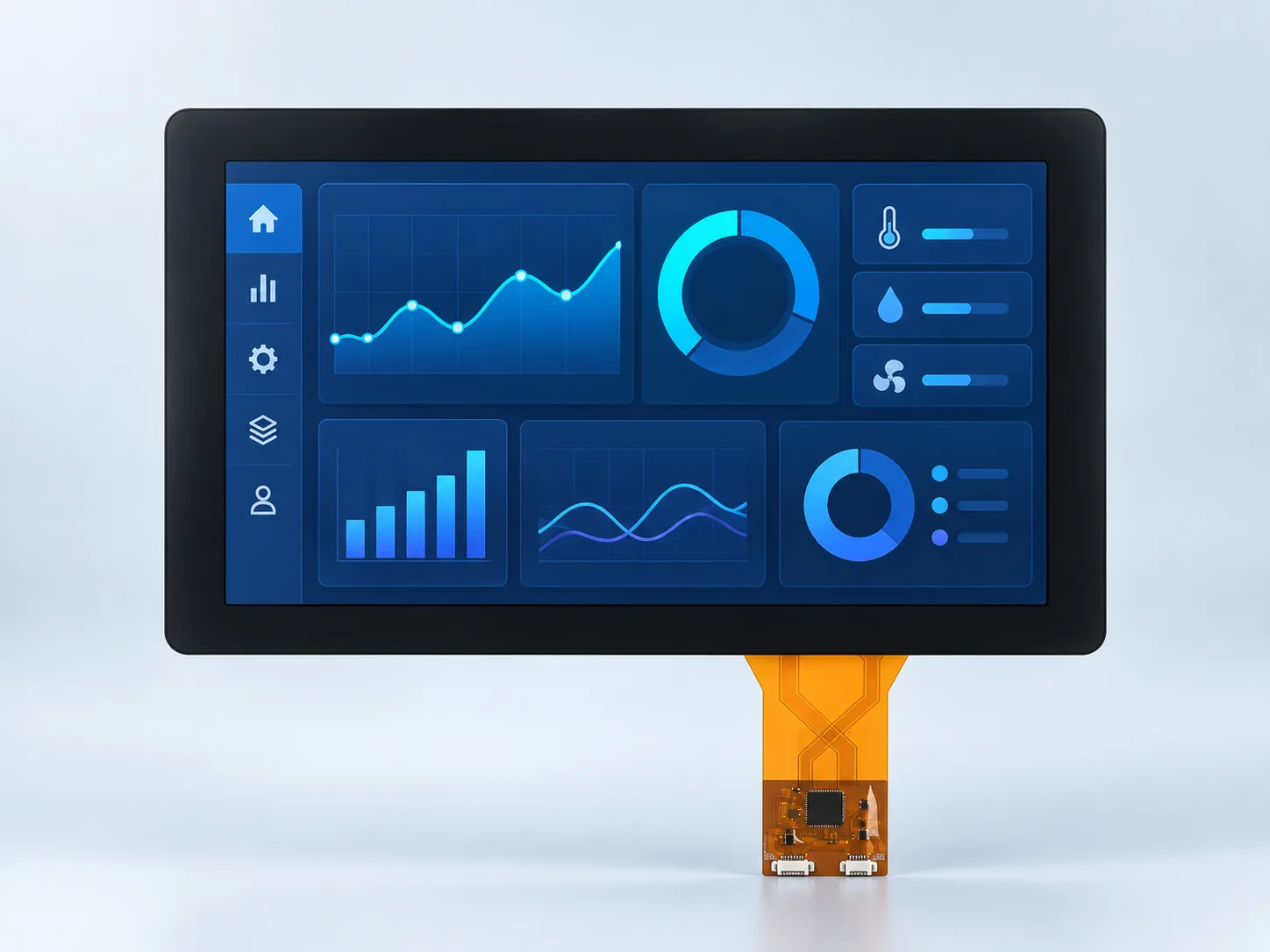
Illustrative industrial HMI concept only; it is not a documented customer deployment or mechanical integration drawing.

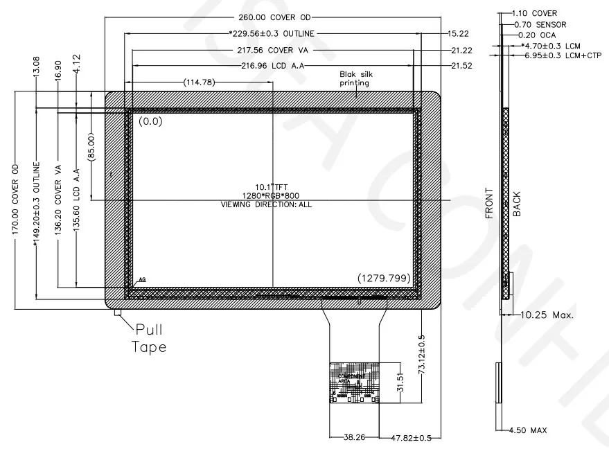
Use the current approved drawing for production release, tolerances and keep-out zones.
Shortlist this verified configuration when the project boundary calls for a 10.1-inch 1280×800 IPS display, an 850 cd/m² target, integrated PCAP touch, optical bonding and the documented 40-pin LVDS connection. The final decision still depends on the host, enclosure, light and temperature conditions.
Verify that the processor or controller supports the exact 1280×800 timing, LVDS mapping, 6/8-bit mode, voltage rails and 40-pin connection. The LVDS integration guide explains why the source, cable, connector and panel must be validated as one link.
This configuration is documented with PCAP and optical bonding. Confirm the ILI2511 controller interface, touch FPC route, cover outline, bezel overlap and intended finger, glove, water and EMC conditions during sample validation.
The documented 260.00×170.00×6.95 mm outline describes the module assembly. Use the current approved drawing—not the diagonal size—to release the opening, supports, connector access, FPC bend and keep-outs.
If the UI needs 1920×1200, compare DS-T101BFHA-01CP. It has 2.25 times as many pixels and a different documented LVDS connector/interface, so host capability and mechanical fit must be checked again.
Need a display without integrated touch? Compare the separately documented DS-T101HIEWA-01 base module at 1000 cd/m². Its outline and front stack differ from this 850 cd/m² CP assembly; do not treat the two as drop-in substitutes.
The documented module interface is LVDS 6/8-bit with a 40-pin connector. Confirm the current pinout, timing, mapping and electrical limits before design-in; the interface name alone does not establish compatibility.
Yes. This verified configuration uses PCAP touch with an ILI2511 touch controller and optical bonding. Review the PCAP selection guide and validate the assembled touch stack in the actual use conditions.
The documented module outline is 260.00×170.00×6.95 mm, and the active area is 216.96×135.60 mm. Use the current approved drawing for tolerances, mounting details and keep-out zones.
This model is documented at 1280×800, 850 cd/m² and LVDS 6/8-bit 40-pin. The separate DS-T101BFHA-01CP is documented at 1920×1200, 1000 cd/m² and dual-channel 8-bit LVDS 45-pin. Compare host bandwidth, pinout, temperature range, stack thickness and thermal conditions before choosing.
Send the host platform, enclosure constraints, target quantity, touch environment and viewing conditions for a fit review.