Separate operating from storage conditions
Record both conditions and the transition or start-up requirement for the finished equipment.
For equipment exposed to low or high temperatures, selection should consider more than the headline operating range.
Define operating and storage conditions, start-up temperature, installation location and duty cycle before comparing module data. Where temperature and bright ambient light coincide, also review high-brightness display considerations. For outdoor visual performance, also review sunlight-readable TFT LCD requirements.
A headline temperature range cannot replace system validation. Confirm operating and storage ranges, low-temperature start-up, duty cycle and backlight behavior against the current approved datasheet.
Record both conditions and the transition or start-up requirement for the finished equipment.
Installation location, thermal design, interface electronics and operating duty can affect the practical margin.
Candidate selection is a first step; the current datasheet and drawing remain the source for production approval. For the broader design-in checklist, use the industrial TFT LCD selection guide.
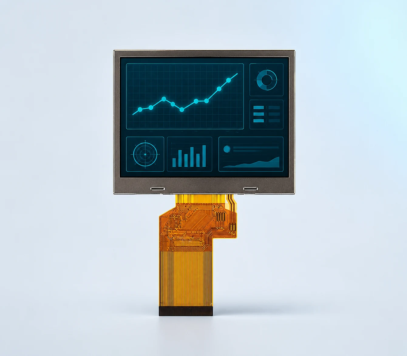
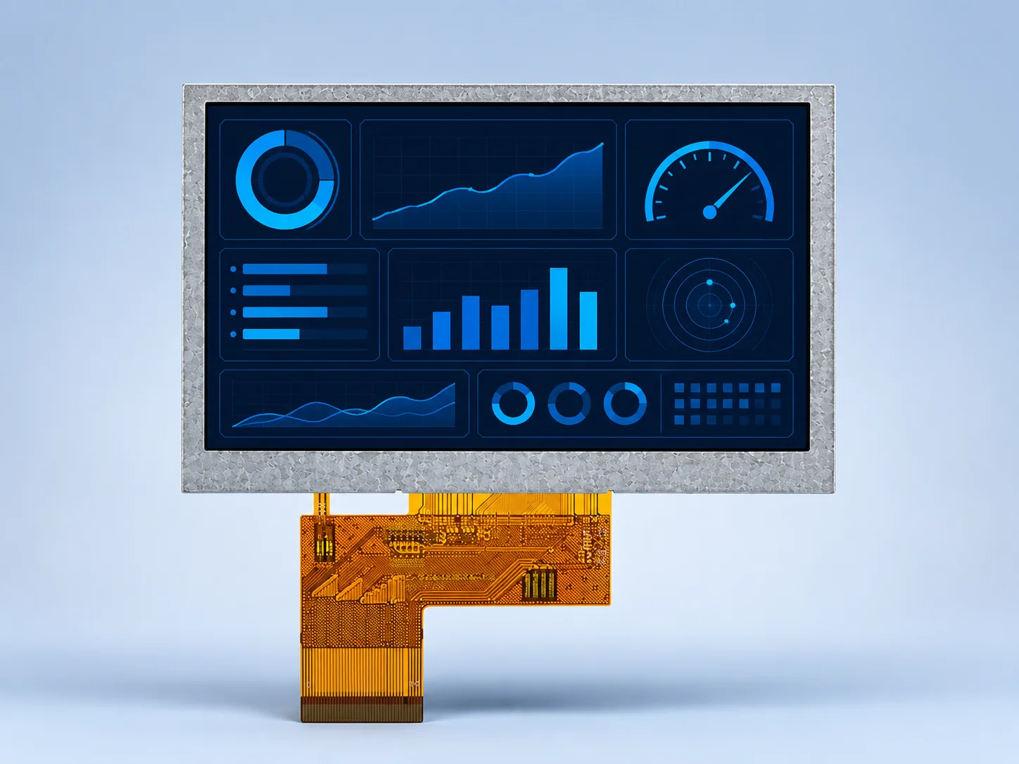
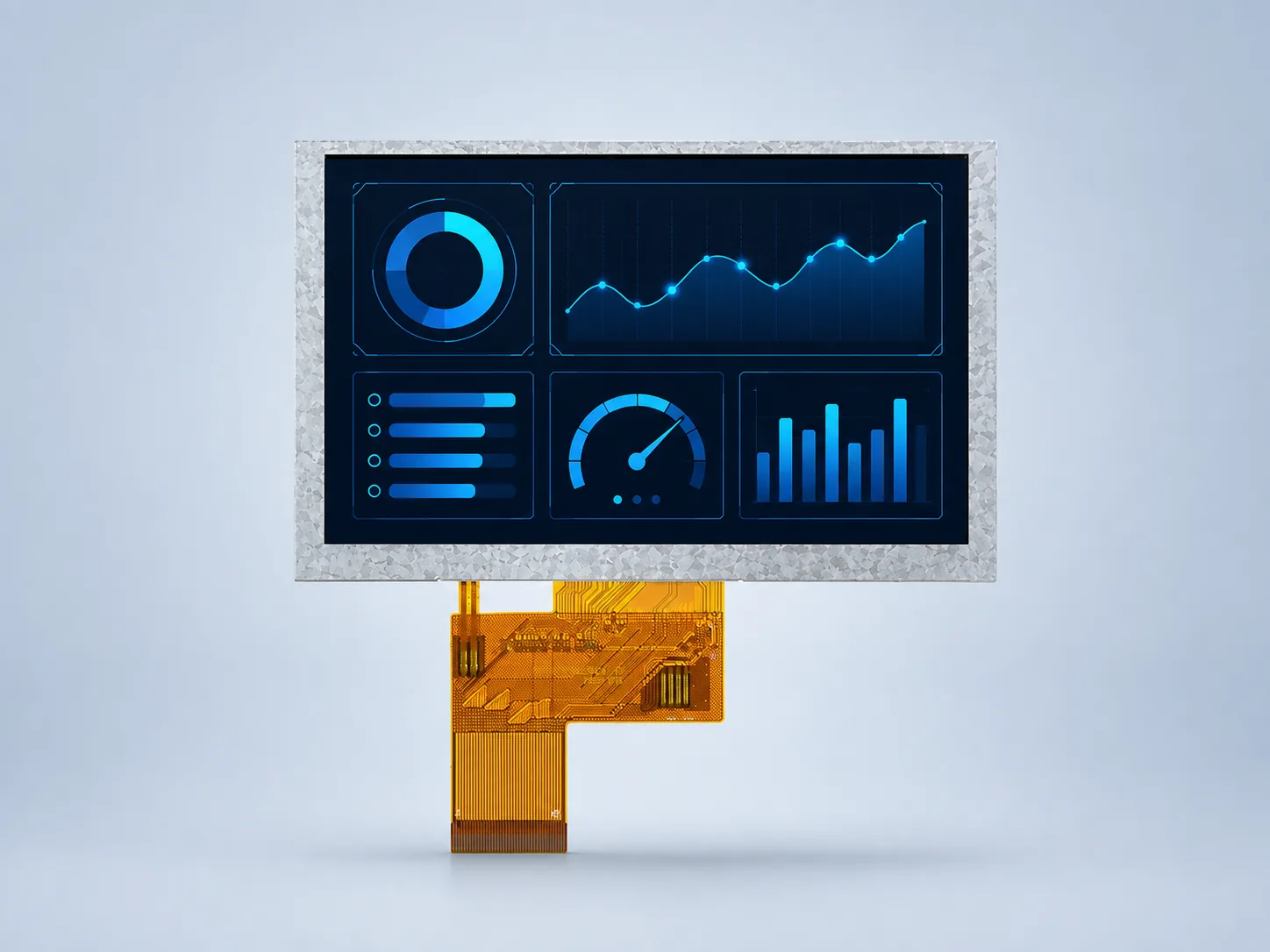
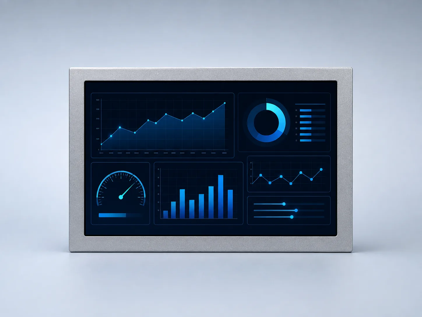
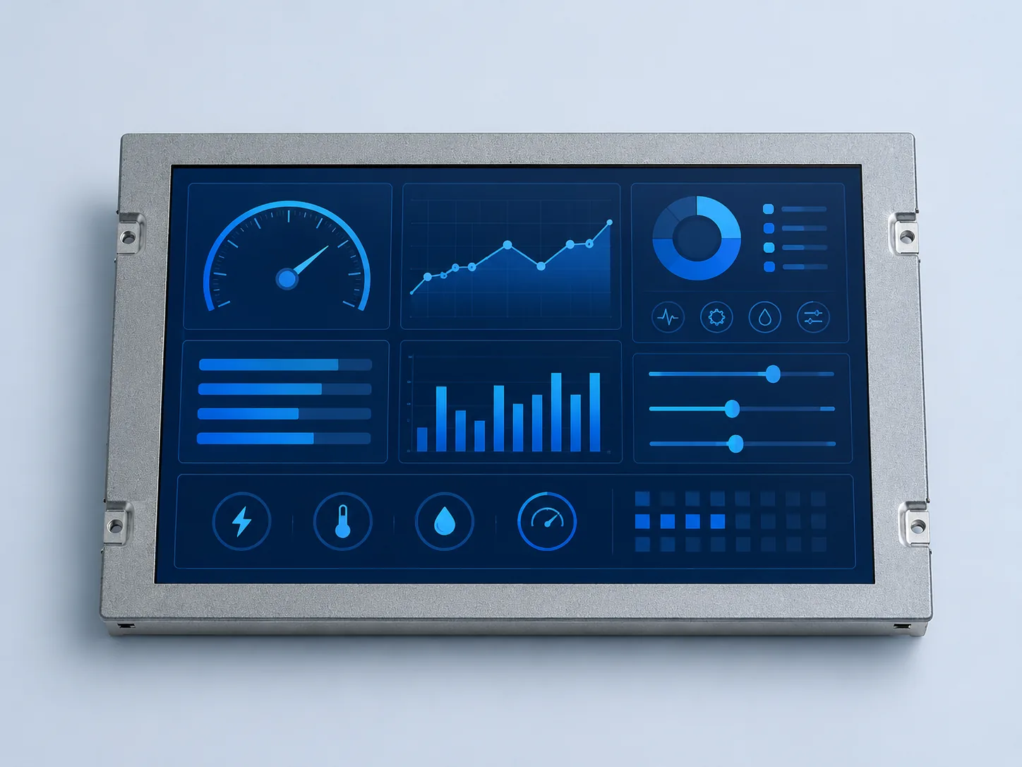

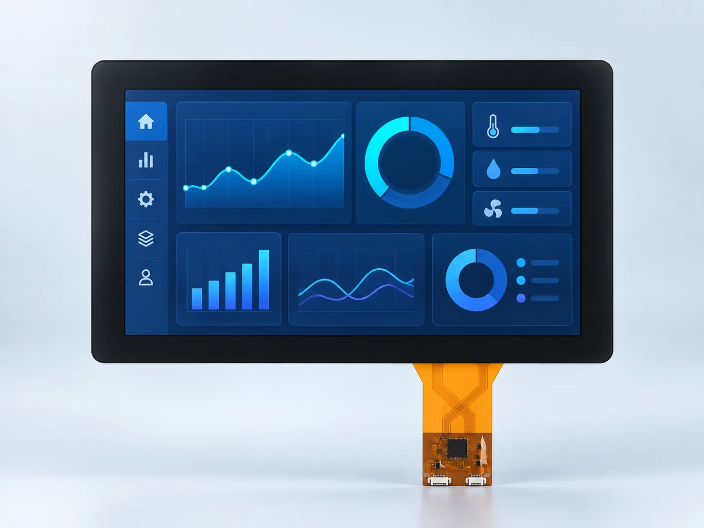

A wide-temperature TFT LCD is approved as part of the finished equipment. Separate the panel limits from start-up behavior, thermal transitions, backlight operation, enclosure conditions and the validation method used for the production configuration.
State whether the display must start, update and reach an acceptable image immediately at the minimum temperature. A published operating range alone does not describe the required start-up time or visual acceptance criterion.
Combine ambient temperature with backlight power, nearby electronics, sealed-air volume and duty cycle. For bright displays, use the high-brightness thermal review.
Confirm storage limits separately and define transitions such as cold storage followed by powered operation. Include condensation control and the time allowed for stabilization in the equipment test plan.
Review the LED drive, dimming range, current limit and temperature condition used for the lifetime statement. The backlight lifetime guide explains which evidence to request.
Touch sensors, cover lenses, adhesives and optical bonding create additional material interfaces. Validate the specified stack across the intended environment instead of extending the bare-panel range to the assembly.
Test the released display, cable or FPC, driver, cover stack and enclosure together. Record temperatures, dwell times, power state and visible acceptance criteria so samples can be compared consistently.
No. The range identifies a documented operating boundary, but cold-start time, image response and the finished system behavior still need a project-specific acceptance test.
No. Storage describes an unpowered condition, while operation includes electrical and optical behavior. Verify both ranges and the transition between them from the current module documentation.
No. The touch controller, cover stack, adhesives, cables, power supplies, processor and enclosure must each support the required environment and be tested as one assembly.
Provide minimum and maximum operating and storage temperatures, cold-start requirement, dwell time, duty cycle, enclosure and heat sources, brightness and dimming needs, touch or bonding stack, host interface and validation standard used by the project.
Use the engineering review to combine optical, mechanical and electrical requirements before sampling.