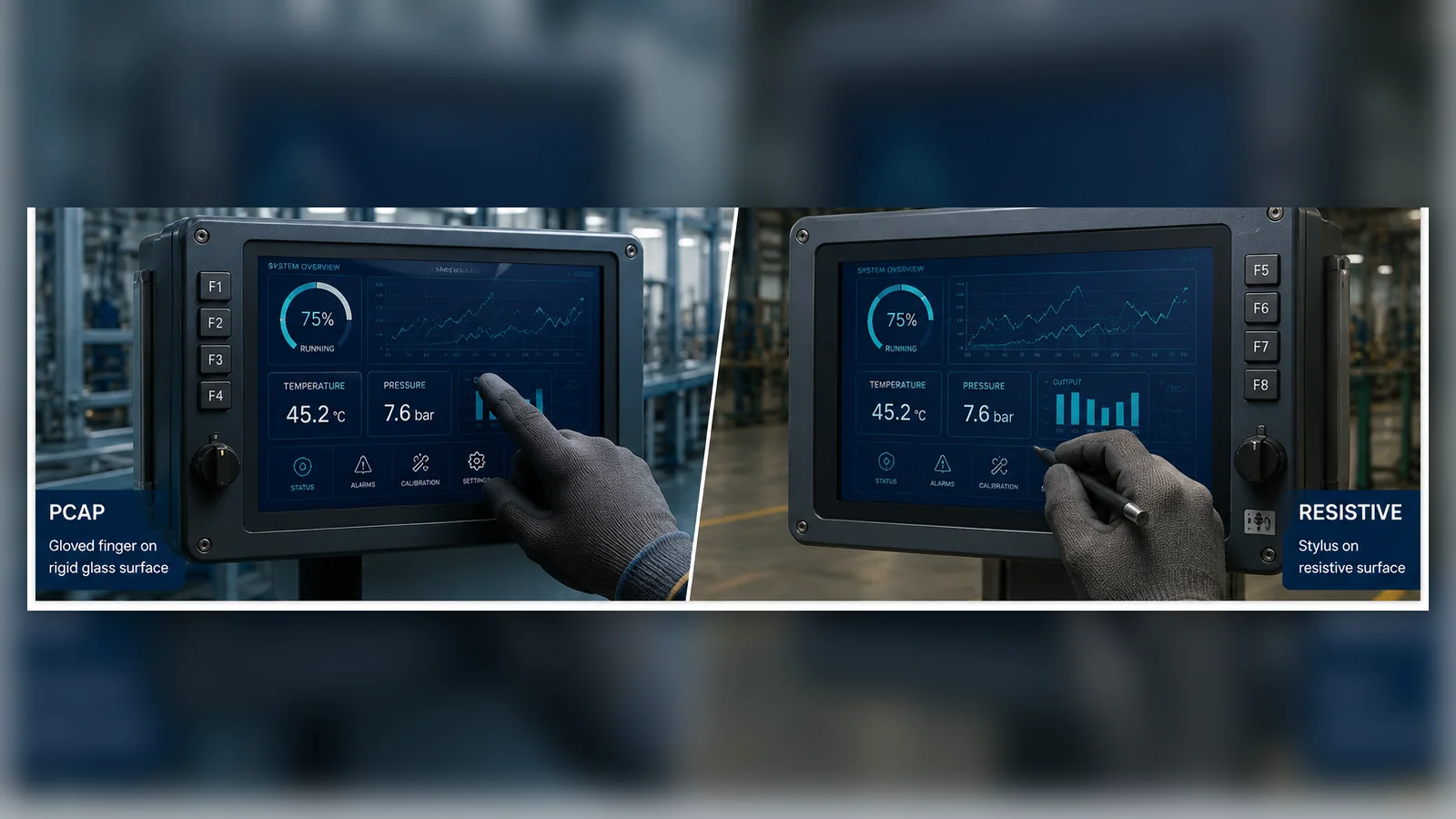
The touchscreen is an operator interface, an optical layer, an electrical subsystem and part of the enclosure. Choosing it only by “capacitive feels modern” or “resistive works with gloves” misses the controller, front glass, noise, sealing and validation work that determines field performance. If the display module is also being selected, start with the seven-specification industrial TFT LCD guide.
PCAP vs resistive touchscreen comparison
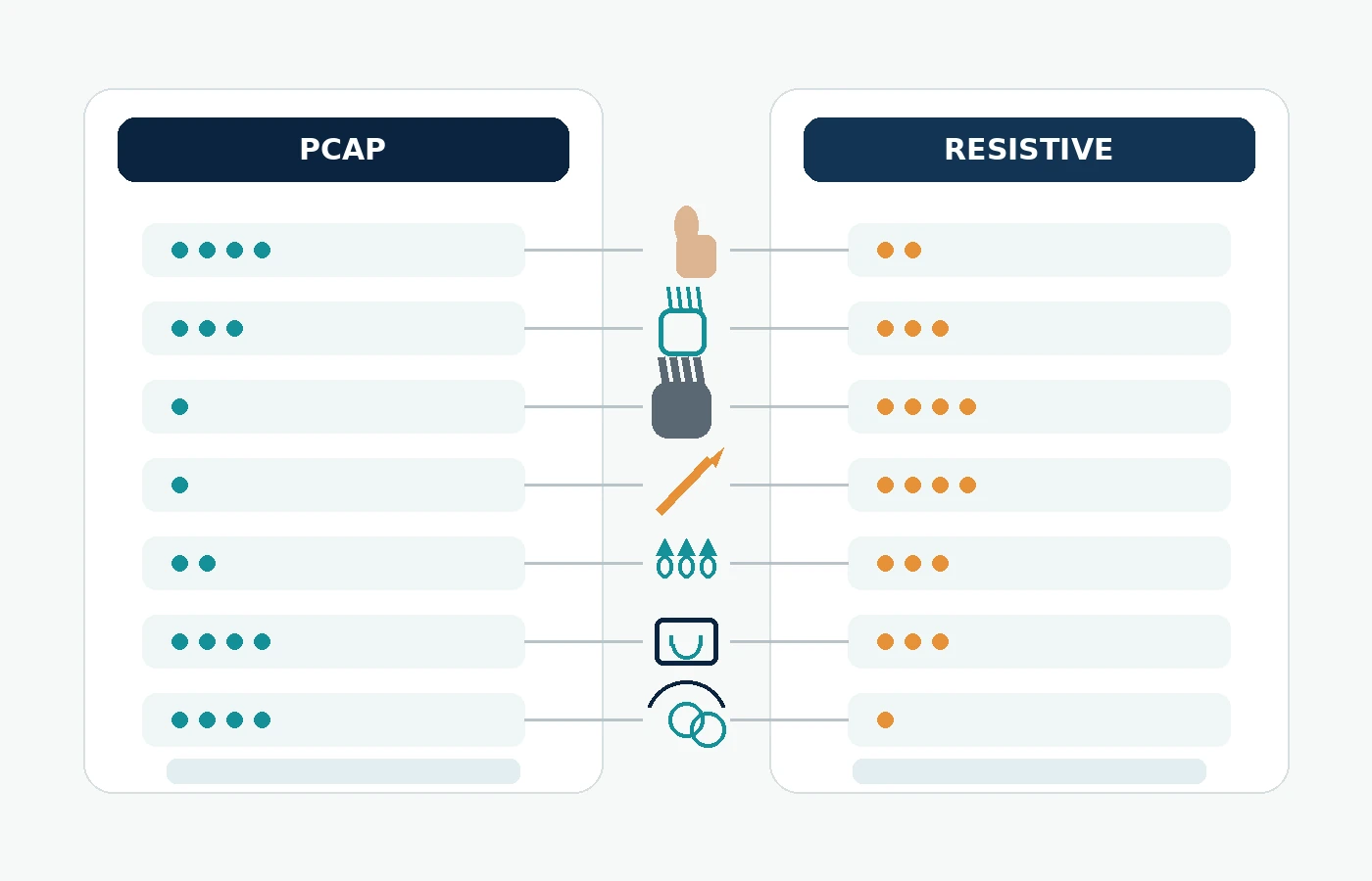
| Decision factor | Projected capacitive (PCAP) | Resistive touch (RTP) |
|---|---|---|
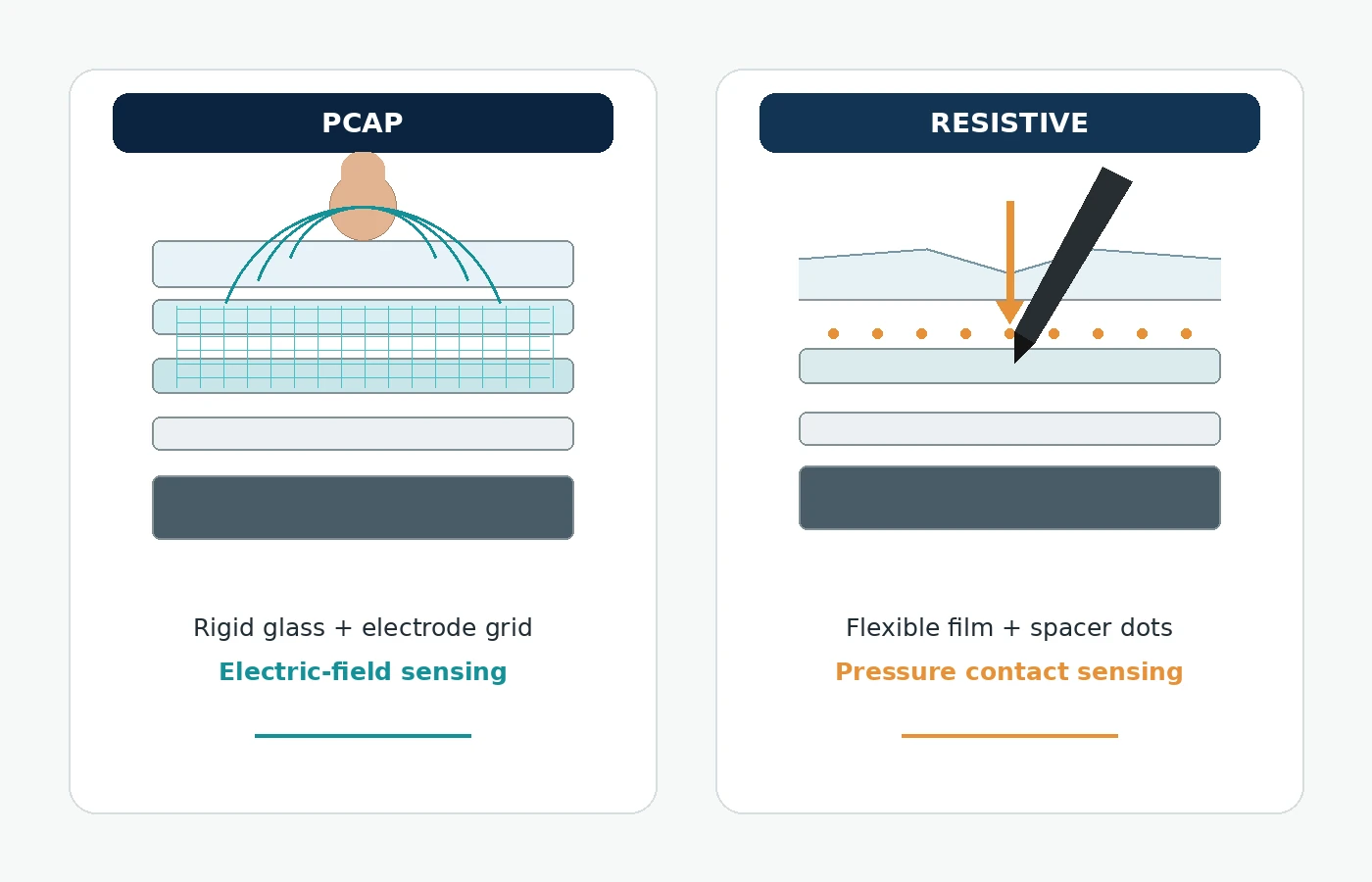
| Detection principle | Detects a change in an electric field through a sensor grid | Detects pressure that brings conductive layers into contact |
| Input | Bare finger; glove and passive-stylus support depend on controller, tuning and stack | Finger, glove or suitable stylus when enough pressure is applied |
| Multi-touch | Commonly supported when controller and firmware allow it | Traditional 4-wire/5-wire industrial designs are generally single-touch |
| Front surface | Can sit behind a continuous cover lens | Uses a flexible touch surface that must deflect |
| Optical design | Works well with a clear cover lens and optical bonding; validate sensor pattern and coatings | Additional flexible layers can reduce transmission and add reflections |
| Noise sensitivity | Controller tuning, grounding and EMC design are critical | Analog coordinate measurement requires attention to display/backlight noise and routing |
| Wet operation | Advanced controllers can support moisture modes, but every design must be tested | Pressure operation can remain practical, but sealing and unintended pressure/water behavior still need review |
| Best fit | Gesture-rich HMI, sealed glass front, premium optical stack | Deliberate single-point control, broad stylus/glove input, simpler UI |
How PCAP works—and what engineers must validate
A projected capacitive sensor forms an electrode matrix behind the front surface. A touch controller measures small capacitance changes and calculates the contact position. This enables fast response and multi-touch without a flexible top film. Because the electrodes sense an electric field, the final cover thickness, glass dielectric properties, printed border, grounding and nearby conductors all affect signal strength.
Industrial PCAP is a system-tuning task. Backlight drivers, chargers, motors, switch-mode supplies and the LCD itself can inject noise. The touch controller, sensor pattern, firmware configuration, shield strategy and mechanical stack must be validated together. A controller family may advertise glove or moisture capability, but that capability does not transfer automatically to every sensor and cover design.
How resistive touch works—and where it remains useful
A resistive panel uses conductive layers separated by small spacers. Pressure brings the layers together; a controller measures the resulting voltage to determine position. Because the action is pressure-based, the operator can typically use a finger, glove or suitable stylus without relying on capacitive coupling.
The tradeoff is mechanical. The top surface must flex, so it cannot behave like a thick, continuous PCAP cover lens. Traditional industrial RTP is generally a single-touch solution, and the analog signals can pick up noise from the display and backlight if layout, grounding and filtering are weak. Coordinate calibration and edge accuracy also need attention.
Gloves, water and cleaning: specify the actual condition
“Glove operation” is not one requirement. A thin nitrile glove, dry work glove and insulated winter glove couple very differently. For PCAP, document the material, thickness, number of glove layers and required touch size. For RTP, document the allowable activation force and whether a stylus is used.
Water also needs a test definition. A few droplets, a wet finger, a continuous film, saltwater and cleaning solution are different electrical conditions. Decide whether the screen must track through moisture, ignore all touch while wet or permit only deliberate presses. Include the cleaning process and chemicals in the cover and sealing review.
Cover lens, optical bonding and perceived image quality
PCAP is well suited to a custom cover lens with printed border, logo, window shape and surface treatment. Optical bonding can remove the air gap between the touch assembly and LCD, reducing internal reflections and eliminating an internal condensation cavity. RTP may also be integrated into a front stack, but its flexible operating surface creates different mechanical constraints.
If bright ambient readability matters, review the full optical system in the sunlight-readable TFT LCD guide, including its optical bonding vs air-gap comparison.
Which touch technology should your HMI use?
Choose PCAP when…
- The product needs a sealed, easy-to-clean glass front.
- Gestures or multi-touch are part of the UI.
- Appearance and optical clarity are priorities.
- The project can support controller tuning and EMC validation.
- Glove and wet behavior can be defined and tested.
Choose resistive when…
- The operator needs reliable pressure input from a glove or simple stylus.
- The UI uses deliberate single-point selections.
- A flexible touch surface is acceptable.
- The system is prepared for analog touch routing, calibration and filtering.
- Mechanical actuation is a better fit than capacitive sensing for the use case.
Three TFTWorks PCAP module examples
The industrial TFT with PCAP category includes verified touch-integrated examples for different optical and mechanical targets:
- DS-T035SGV-01CP: 3.5-inch 640×480 IPS, PCAP with ST1633i controller and optical bonding.
- DS-T043BPSA-02CP: 4.3-inch 480×272 IPS, 850 cd/m², PCAP with ILI2310 controller and optical bonding.
- DS-T050BWSA-02CP: 5-inch 800×480 IPS, 900 cd/m², PCAP with ST1633i controller and optical bonding.
For each model, confirm the current touch interface, pinout, cover dimensions and approved drawing before design-in. If resistive input is the better fit, review the industrial TFT with resistive touch category and share the input tool and sealing requirements.
Information to include in a touch-display RFQ
- Operator input: finger, exact glove type, stylus type and required gestures.
- Exposure: droplets, wet finger, cleaning fluid, dust and ESD/EMC environment.
- Cover lens: material, outline, thickness, printed border, coatings and logo.
- Host interface: I²C, USB, SPI or other available connection and voltage.
- Mechanical stack: bonding method, total thickness, gasket, bezel and touch-tail route.
- Acceptance tests: touch points, edge performance, noise sources, temperature and wet/glove modes.
Technical references
- Microchip maXTouch touchscreen controllers: examples of moisture, noise and glove capabilities that must be engineered at controller-and-stack level.
- Texas Instruments — PCB Layout Guideline for Resistive Touchscreen Controllers: layout, noise and grounding considerations for resistive touch systems.
- Texas Instruments — Reducing Analog Input Noise in Touch Screen Systems: explains display and backlight noise coupling into resistive touch measurements.