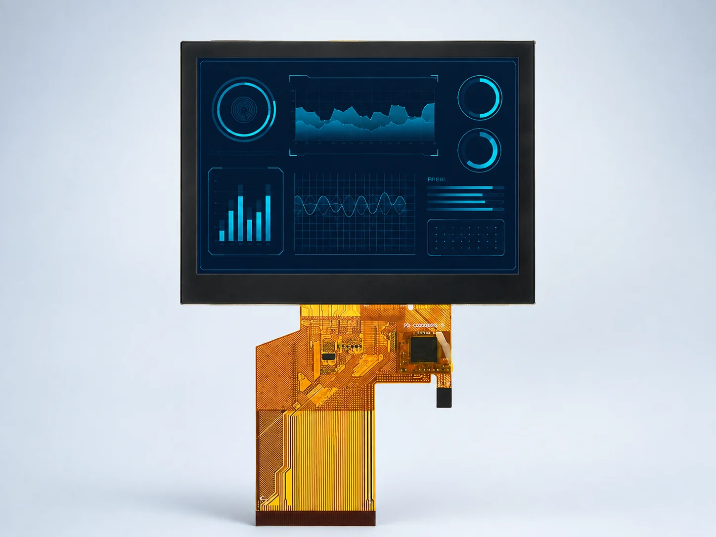
3.5 inchIPS
DS-T035SGV-01CP
640×480 VGA · 320 cd/m²
RGB 24-bit, 54-pin
PCAP / CTP · Optical bonding
Source a TFT LCD module for medical equipment around the actual UI, host output and front-panel configuration. Compare component candidates, then request the exact assembly documents and sample acceptance review; a module listing is not a medical-device approval.
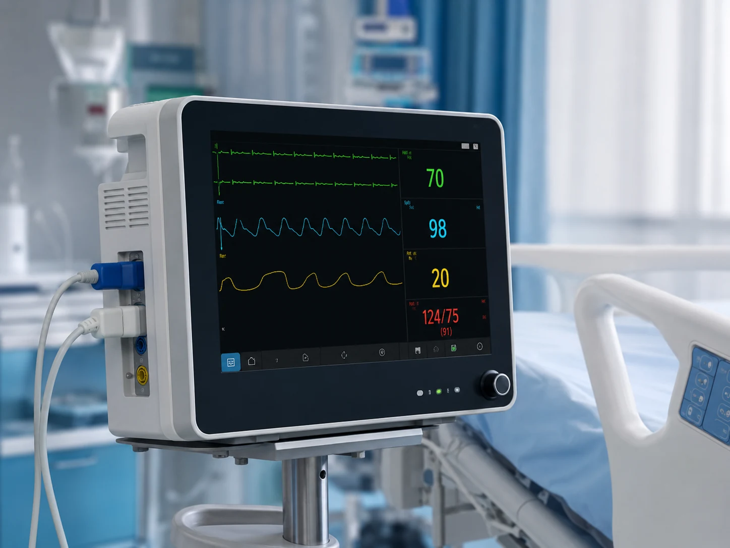
These are component candidates, not medical-approved systems or evidence of use in a specific customer device. Define legibility, cleaning agents, touch method, color/display acceptance and system risk controls. Request applicable supplier quality documents with their legal entity, scope and validity; they do not replace equipment-level compliance assessment.
If a medical-equipment interface requires wet cleaning, use the washdown HMI touchscreen design guide when defining the display front stack and enclosure tests. A PCAP module does not establish the equipment’s sealing or medical compliance.
| Model | Size / resolution | Panel / luminance | Display interface | Touch / bonding | Operating range | Why review it |
|---|---|---|---|---|---|---|
| DS-T035SGV-01CP | 3.5 inch 640×480 VGA | IPS 320 cd/m² | RGB 24-bit, 54-pin | PCAP / CTP Optical bonding | −20 to 70 °C | Compact 640×480 RGB bonded PCAP candidate; 320 cd/m² configuration |
| DS-T050BWSA-02CP | 5.0 inch 800×480 | IPS 900 cd/m² | RGB 24-bit, 40-pin | CTP / PCAP Optical bonding | −20 to 70 °C | 5-inch 800×480 bonded PCAP candidate for a compact operator interface |
| DS-T101HIEWA-01CP | 10.1 inch 1280×800 | IPS 850 cd/m² | LVDS 6/8-bit, 40-pin | CTP / PCAP Optical bonding | −30 to 85 °C | 10.1-inch 1280×800 LVDS bonded PCAP candidate for a larger interface |
Luminance belongs to the exact listed configuration. It is not a finished-system sunlight-readability, sealing, EMC or safety certification. “No TP” means no integrated touch panel is documented.
RGB 24-bit, 54-pin
PCAP / CTP · Optical bonding
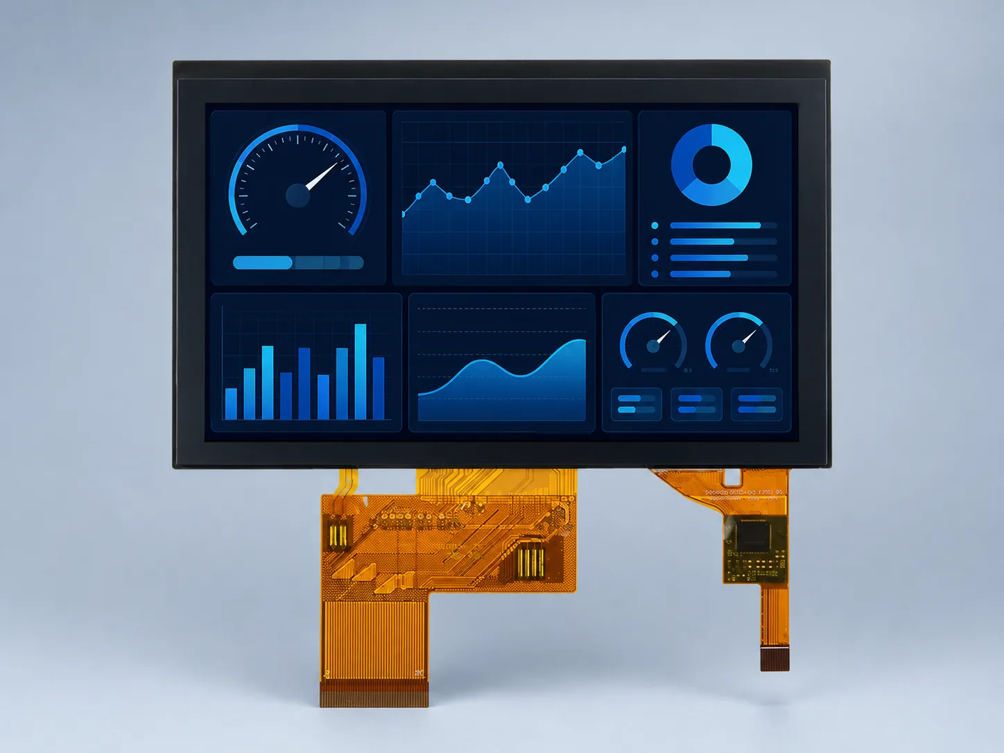
RGB 24-bit, 40-pin
CTP / PCAP · Optical bonding
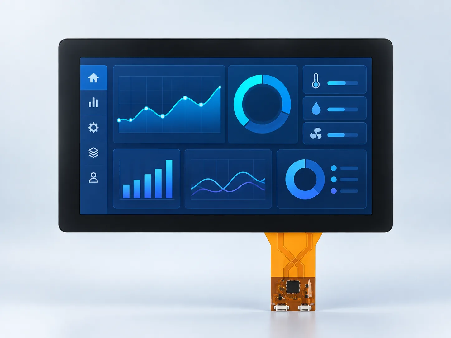
LVDS 6/8-bit, 40-pin
CTP / PCAP · Optical bonding
A medical-equipment LCD module should be shortlisted around the operator’s task, not a “medical-grade” label. Describe what the user must read or select, then review the candidate in the intended host and front panel. The checks below are planning inputs, not completed tests or a device approval.
On smaller screens, scroll the table horizontally to compare all three columns.
| Use condition | Define in the requirement | Record during sample review |
|---|---|---|
| Shared or angled viewing | Operator positions, viewing distance, mounting angle and the smallest important text or symbol in the actual UI. | Read the same representative screens at the agreed positions; record unreadable text, contrast changes and open issues. See the IPS versus TN viewing guide. |
| Low-light use | Required brightness adjustment, start-up behavior and any camera or audible-noise constraints. | Review the dimming range on the selected driver and host with the real UI. The backlight-dimming guide explains what to ask; the module’s listed luminance alone does not specify its dimming behavior. |
| Gloved operation and cleaning | Exact glove and input method, cover-lens drawing, cleaning agents, exposure and required behavior while the surface is wet. | Record touch misses, unintended input and visible surface changes against agreed criteria on the final stack. Compare PCAP and resistive sample checks before choosing a touch label. |
| Configuration release | Display and touch connections, assembly drawing, host revision and the documents required by the equipment team. | Keep the reviewed sample configuration and document revisions together. Use the configuration-specific document requests; a catalog summary is not a controlled assembly drawing. |
For a compact native-RGB host, compare DS-T035SGV-01CP (640×480) with DS-T050BWSA-02CP (800×480). Their UI resolution and published front-stack specifications differ. For a larger native-LVDS interface, DS-T101HIEWA-01CP is a separate 1280×800 bonded-PCAP candidate. Use the 10.1-inch assembly purchasing checks before reusing a host or enclosure. Ask for the exact drawing and separate touch connection; size and PCAP labels do not establish interchangeability.
Include the device’s UI task, operator positions, host output, cover opening, glove and cleaning conditions, sample stage and target quantity. Remove patient identifiers from UI screenshots. State any diagnostic-imaging or safety-critical requirement explicitly for the equipment team’s review; this page does not establish suitability for that use.
The review form preselects Medical Equipment and provides editable prompts. It accepts text, not file attachments; send the drawing or de-identified screenshot by email or WhatsApp with the same project reference. Checklist updated October 14, 2026.
Start with the selected IPS module and identify any requested touch, cover-glass or FPC changes. For a medical device LCD supplier review, request current model documents, configuration control and an agreed sample acceptance plan. Assess suitability within the complete equipment design.
Choose touch and cover geometry from the exact model.
Explore this selection path →Record system-specific optical, electrical and environmental criteria.
Explore this selection path →Ask which documents apply to the supplier, configuration and project.
Explore this selection path →For an OEM medical-equipment display, separate the component shortlist from the device acceptance decision. The listed 3.5-inch VGA PCAP, 5-inch 800×480 PCAP and 10.1-inch 1280×800 PCAP candidates use RGB or LVDS and have different luminance, outlines and temperature limits. Shortlist by the actual UI, host and front-panel constraints, then define viewing, glove, cleaning and electrical acceptance. An application label does not establish diagnostic suitability, medical-device approval or validated performance in your equipment.
Compare bare finger, glove, stylus, water exposure, cover glass and controller requirements.
Compare touch technologies →Evaluate readability, reflections, adhesive choice, tolerances and bonding validation before release.
Review optical bonding →Record the exact module, touch, cover lens, interface, drawing and sample configuration under review.
Use the requirements checklist →Brightness, backlight, FPC, interface, touch, cover glass, optical bonding and driver-board options should be considered only where the project requires them.
The three module configurations above are published component references. Before design-in, connect the exact display and touch assembly to current documents and a recorded review of your equipment’s actual operating conditions.
Use each linked model page to trace the listed interface, luminance, touch and operating range. The DISEA standard module catalog, DS series 2026 V2.1, is a summary reference rather than a controlled drawing or a medical-device approval.
Request the current display datasheet, separate touch connection, cover-lens or assembly drawing and applicable supplier documents for the exact model. Keep their revisions and the reviewed configuration with your project.
Record the representative UI, operator positions, dimming settings, glove and cleaning conditions, host board and complete front stack used in the review. Agree the acceptance criteria with the equipment team before recording a pass or an open issue.
For low-light operation, describe the required dimming behavior and share representative UI screenshots with the PWM versus analog backlight-dimming guide as a planning reference. Use the IPS versus TN viewing guide to identify the operator positions to review, and the industrial PCAP design guide for glove, moisture and cover-lens inputs.
These links provide catalog references, document requests and a blank review record; they do not publish test results for your finished equipment. The web form accepts text details. Send drawings or UI screenshots by email or WhatsApp with the same model and project reference.