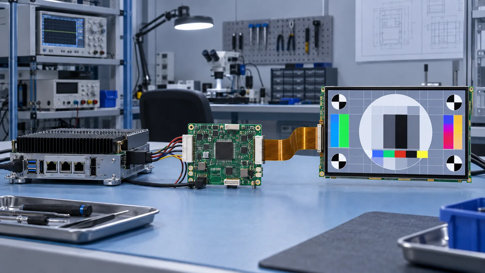
“TFT LCD controller board” can describe several different products. It may be a monitor-style board that accepts HDMI or DVI, an embedded processor board with a native display peripheral, a bridge board that changes one interface into another, or a controller that stores pixels for an MCU-driven module. Before comparing boards, define which system boundary you actually need.
If the panel has not been selected, begin with the RGB, LVDS, MIPI DSI and MCU interface guide and the industrial TFT interface overview. If the panel is fixed, its current datasheet, timing table, pinout, initialization data and backlight specification become the starting requirements for the board.
The short answer
A compatible controller board must accept the host’s real video or data output and generate the panel’s exact native interface. It must support the native resolution and timing, pixel mapping, I/O voltage, power sequence, backlight load, dimming method and any panel-specific initialization. It also needs enough bandwidth, memory and thermal margin for the required UI, environment and lifecycle.
Four common controller-board architectures
| Board type | What it does | Key risk |
|---|---|---|
| Monitor-style controller | Accepts an external video input, may scale it, and generates a panel link. | Panel timing, firmware profile, scaling behavior and backlight support may be fixed. |
| Embedded processor or SBC | Renders the UI and drives a native RGB, LVDS, DSI or eDP output. | The processor may lack the required display peripheral, memory bandwidth or driver support. |
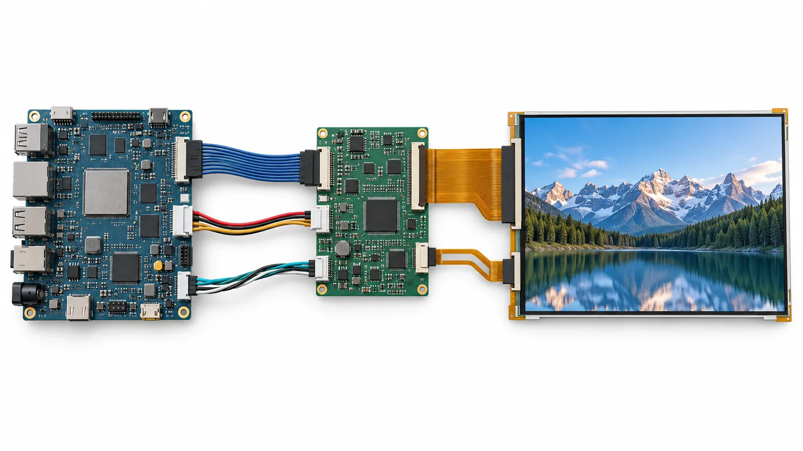
| Interface bridge board | Translates one electrical/protocol family into another. | A bridge changes the interface, but it does not automatically solve timing, mapping, initialization or power. |
| Display-memory controller | Accepts MCU/SPI commands and pixel writes, then refreshes the panel. | Update rate, controller command set and graphics-memory limits can constrain the UI. |
Freeze these inputs before requesting a board
- Host source: exact processor, GPU or equipment output; connector; signal standard; supported modes and operating system.
- Panel identity: full TFT model and suffix, current datasheet, mechanical drawing and revision.
- Native panel link: RGB width and timing, LVDS channel/mapping, DSI lane/mode/init sequence, or other exact definition.
- Image requirement: native resolution, target refresh rate, color depth, rotation, scaling and latency.
- Power: input supply, panel rails, reset/enable sequence and maximum load at startup and operation.
- Backlight: LED string voltage/current, number of strings, dimming input, enable polarity and brightness range.
- Touch: PCAP/RTP controller, USB or I²C connection, firmware, noise environment and cable route.
- Industrial constraints: operating temperature, vibration, EMC/ESD, enclosure, mounting, lifecycle and service method.
Match the native panel interface
Parallel RGB
The board must generate the required pixel clock, DE, HSYNC, VSYNC, porch values, polarity and RGB bit order at the panel’s I/O voltage. “24-bit RGB” does not define connector pinout or timing. Use the RGB TFT LCD timing guide to build the controller configuration.
LVDS
Confirm single- or dual-channel operation, clock range, mapping convention, color depth, pair order and polarity. The cable and connector are part of the link. Review the LVDS cable-length guide before releasing a production harness.
MIPI DSI
MIPI DSI compatibility includes lane count, lane rate, D-PHY timing, command/video mode, clock behavior, packet format and panel-specific initialization. A generic HDMI-to-DSI board is not automatically compatible with every DSI display. Follow the MIPI DSI lane-selection workflow and confirm that the board firmware supports the exact module revision.
MCU or SPI
Confirm controller IC, bus mode, write timing, SPI mode, bit order, reset sequence, address windows and pixel format. Estimate the real frame-update requirement rather than assuming the bus clock equals usable image bandwidth.
Resolution support is not timing compatibility
Two panels with the same active resolution can require different pixel clocks, porches, polarities and refresh ranges. A controller-board listing that says “supports 1280×800” does not establish compatibility with every 1280×800 TFT. Obtain the board’s configurable timing limits and a panel profile for the exact model.
For a continuous video path, begin with the panel totals:
Then check the bandwidth of the input receiver, scaler, framebuffer, memory interface and panel transmitter. Rotation, scaling, overlays and double buffering add work beyond the active-pixel calculation. Test under the real processor and graphics workload.
Firmware, EDID and initialization
Monitor-style boards may present EDID to an HDMI/DVI source so the host can choose an input mode. That source-side exchange does not configure the raw TFT by itself. The board still needs the correct panel timing, mapping, output format, power sequence and backlight parameters.
DSI and controller-based MCU/SPI panels can require model-specific register tables. Ask how firmware is identified, version-controlled, updated and restored. Confirm whether a field update can leave the screen unusable and how the production board is programmed.
Panel power and backlight are separate design tasks
A board that produces correct pixels can still damage or misoperate a display if its panel rails, reset order or backlight driver are wrong. Compare every required voltage, tolerance, ramp and enable relationship with the panel document. Do not connect the backlight until the driver’s current regulation, compliance voltage, string arrangement and connector pinout are verified.
Specify PWM frequency and polarity, analog dimming behavior, minimum stable duty cycle and startup state. Evaluate audible noise, camera-band interaction, thermal rise and EMC in the final enclosure. If brightness is an outdoor requirement, review the 800 vs 1000 vs 1200 nits selection guide before sizing the backlight and power supply.
Why one board cannot be assumed to fit another TFT
Verified TFTWorks modules illustrate the difference. The DS-T070TISA-01 7-inch 1280×800 module uses an LVDS panel interface, while the DS-T078VYRA-01 7.8-inch 400×1280 bar module uses 4-lane MIPI. A controller configured for one is not automatically suitable for the other. Confirm each current datasheet and drawing before design-in.
Industrial requirements beyond first image
- Board and component temperature ratings must cover the actual enclosure temperature, not only room-temperature bench use.
- Input protection, grounding, cable shielding and PCB layout must support the project’s EMC and ESD plan.
- Mounting holes, connector access, cable bend radius, airflow and service clearance must fit the enclosure.
- Boot time, no-signal behavior, image retention at source loss, watchdog recovery and power-cycle behavior must be defined.
- Board revision, firmware revision and approved alternates must be controlled for production and lifecycle support.
A practical controller-board selection workflow
- Freeze the host output and the exact TFT module.
- Create a source-to-panel block diagram, including scaler/bridge, memory, touch, panel rails and backlight.
- Compare native interface, voltage, timing, mapping, initialization and connector pinout line by line.
- Calculate pixel and memory bandwidth for the real resolution, frame rate, color depth and graphics functions.
- Verify the backlight driver and power sequence independently from the image path.
- Obtain the exact board schematic or interface specification and a controlled firmware profile.
- Prototype with production-intent cables, power supply, enclosure and software.
- Validate startup, image patterns, touch, thermal, EMC and recovery behavior before release.
Validation before design release
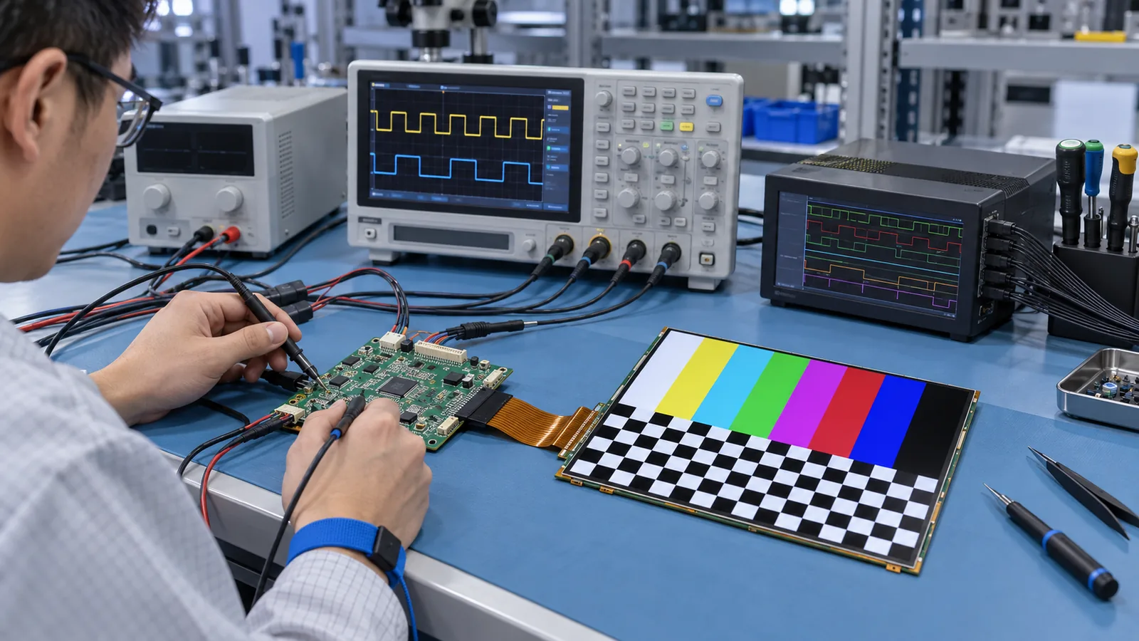
Use solid red, green and blue, grayscale ramps, one-pixel grids, checkerboards, moving video and source-mode changes. Check geometry, color mapping, scaling artifacts, frame drops and input reacquisition. Cycle power in different orders and verify behavior when the source appears late, changes resolution or disconnects.
Measure panel rails, reset, clock/timing or serialized-link status, backlight current and temperature. Repeat at voltage and temperature limits required by the project. If the first image is missing or corrupted, follow the industrial TFT LCD interface troubleshooting guide and change one controlled variable at a time.
Common controller-board selection mistakes
- Matching only resolution and connector shape.
- Confusing HDMI source input with the TFT’s native panel interface.
- Assuming EDID replaces the panel timing and firmware profile.
- Ignoring LVDS mapping or DSI initialization because an image appeared once.
- Driving a backlight from an unverified voltage output instead of a compatible current regulator.
- Approving a room-temperature development board without enclosure, EMC or lifecycle validation.
What to send for a controller-board review
- Exact TFT model, suffix, datasheet, drawing and sample photo.
- Host device and required input connector/signal.
- Native resolution, refresh rate, rotation, scaling and latency requirement.
- Panel interface definition, timing table, pinout and initialization data.
- Input supply, panel rail sequence and backlight electrical specification.
- Touch interface and operating-system/driver requirement.
- Enclosure drawing, cable route, temperature and EMC requirements.
- Annual quantity, lifecycle target and required firmware-update method.
Use the TFTWorks engineering page to review a driver-board or interface-adaptation path, then send the controlled documents for project review.
Technical references
- NXP — i.MX RT eLCDIF RGB Mode Use Case (AN12302): RGB timing, framebuffer and display-controller configuration.
- Texas Instruments — DS90C385A LVDS Transmitter: an official example of converting parallel RGB/control data into an LVDS panel link.
- Texas Instruments — TFP401/TFP401A Digital Receiver: source-side DVI/HDMI video reception, pixel output and EDID context.
- MIPI Alliance — Display Serial Interface: official DSI protocol and physical-layer overview.