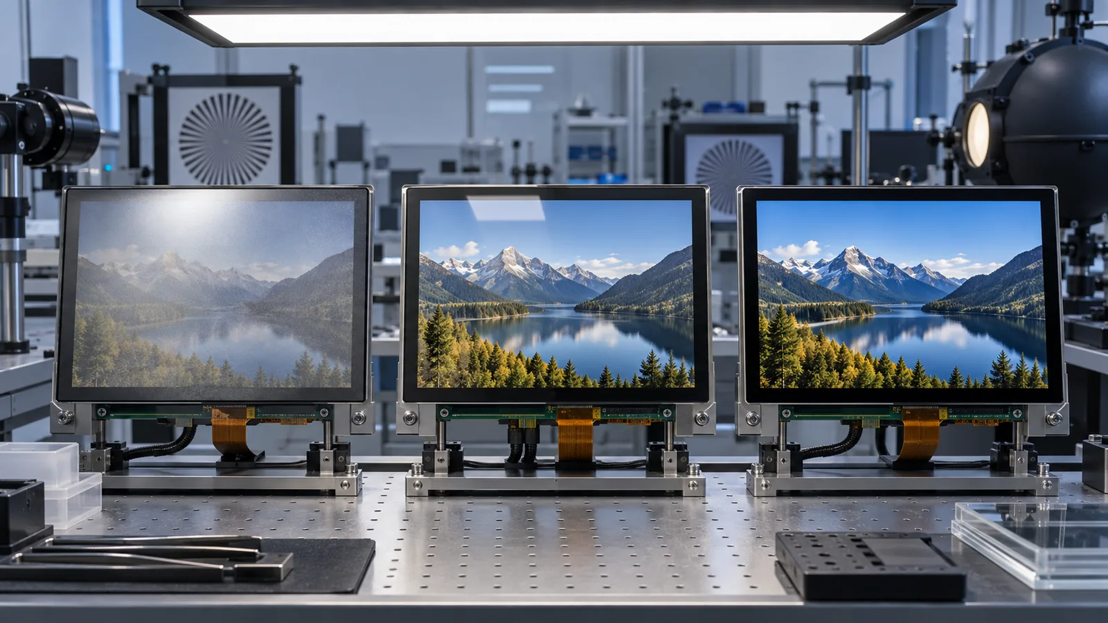
Industrial TFT projects often start with a vague request such as “make the screen anti-glare” or “use optical bonding for sunlight readability.” These phrases hide different optical mechanisms and different engineering risks. Selecting the wrong solution can trade a sharp reflection for haze, preserve clarity but leave an internal air gap, or add bonding cost without solving the dominant top-surface reflection.
This guide compares the three options directly. For the broader relationship between luminance and ambient contrast, read What Makes a TFT LCD Sunlight Readable?.
The short answer
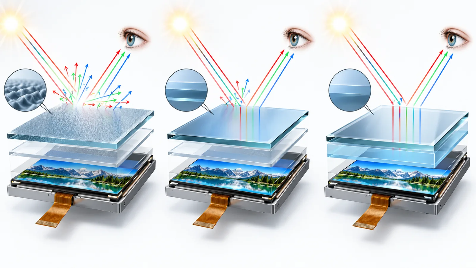
- Anti-glare (AG) uses a matte or micro-textured surface to scatter mirror-like reflections over a wider angle.
- Anti-reflective (AR) uses an optical coating or engineered surface to reduce the amount of light reflected toward the viewer.
- Optical bonding fills an internal air gap between the TFT, touch panel or cover lens to reduce reflection from internal boundaries.
Choose the mechanism that addresses the dominant reflection path. Combine options only after evaluating their cumulative transmission, haze, sharpness, color, durability, touch and manufacturing effects.
AG vs AR vs optical bonding at a glance
| Option | Primary mechanism | Potential benefit | Main tradeoffs to verify |
|---|---|---|---|
| Anti-glare | Scatters incident and reflected light using a textured or diffusing surface. | Reduces distinct mirror images and makes overhead-light reflections less distracting. | Haze, sparkle, loss of fine-detail contrast, surface feel, cleanability and gloss consistency. |
| Anti-reflective | Reduces reflected intensity using an optical thin-film or other engineered surface. | Preserves a clearer, glossier image while reducing top-surface reflection. | Coating durability, fingerprints, abrasion, cleaning chemicals, angular/color behavior and cost. |
| Optical bonding | Replaces an internal air gap with optically clear bonding material. | Reduces internal reflections and improves integration of display, touch and cover layers. | Material compatibility, bubbles, yield, stress, environmental reliability, repair and change control. |
Anti-glare: diffuse the reflection
An AG surface contains fine texture that scatters incoming light. Instead of seeing a sharp lamp, window or face reflected from the screen, the viewer sees a broader, lower-detail patch. This can improve comfort and task visibility in factories, kiosks and control rooms with fixed overhead lighting.
The incident light has not disappeared; it has been redistributed. Too much haze can spread light across displayed pixels and lower perceived black level or local contrast. Fine-pitch displays may show sparkle or grain when the surface texture interacts with the pixel structure. Review small text, thin lines, grayscale ramps and off-axis viewing—not only colorful marketing images.
AG can be created by etched or coated cover glass, a hard-coated film, or another specified front surface. These are not automatically equivalent. Ask for haze, gloss, transmission, clarity or distinctness-of-image metrics where appropriate, plus abrasion, chemical-cleaning and cosmetic-uniformity requirements.
Anti-reflective: reduce reflected intensity
AR treatments are designed so that less incident light returns as a visible surface reflection. Thin-film approaches use controlled optical layers and interference effects. Compared with a strongly matte AG surface, AR can preserve high clarity and fine-detail contrast while keeping a glossy appearance.
Performance can depend on wavelength and viewing angle. Coating hardness, edge handling, fingerprints, oleophobic behavior and cleaning chemistry also matter in industrial equipment. A low-reflection sample that looks excellent when new is not acceptable if routine wiping, abrasion or field contamination quickly changes the surface.
Do not assume that an “AR” label defines a common reflectance value. Specify the measurement method, wavelength or illuminant, angle, coated side, substrate and whether the requirement applies to a single surface or the full assembly.
Optical bonding: remove an internal air gap
Optical bonding fills the gap between layers using an optically clear adhesive or resin. Matching the optical path more closely can reduce reflections at the internal boundaries, improve transmission and reduce visible separation between touch surface and pixels. It can also eliminate the open cavity in which internal fogging or contamination could appear.
Bonding does not treat the top surface by itself. A bonded display with untreated glossy cover glass may still show a strong mirror reflection. It also does not automatically provide enclosure sealing. For material choice, process, failure modes and qualification, use the dedicated optical bonding design-review guide.
Can AG, AR and optical bonding be combined?
Yes. A common engineering objective is to reduce internal reflections with optical bonding and control the outer surface with AG or AR. Some surface systems combine anti-glare and anti-reflective behavior. The combination must be validated as a complete stack because each layer can change transmission, haze, sharpness, color, touch visibility and cleaning behavior.
| Design direction | Where it may fit | What to watch |
|---|---|---|
| AG only | Indoor equipment where sharp overhead-light images are the primary distraction. | Haze, sparkle, small text, contrast and surface cleaning. |
| AR only | High-clarity UI where reducing top-surface reflection matters and a glossy image is acceptable. | Coating durability, fingerprints, angular color and cleaning chemicals. |
| Optical bonding only | Projects dominated by internal air-gap reflection, parallax or cavity concerns. | Untreated top-surface reflection and all bonding process risks. |
| Bonding plus AG | Rugged HMI requiring fewer internal reflections and diffused mirror images. | Cumulative haze, fine-detail contrast and sparkle. |
| Bonding plus AR | Bright-light display requiring low reflection while preserving clarity. | Cost, coating durability, handling and full-stack environmental life. |
There is no universal “best” stack. A bright outdoor display, medical HMI, vehicle console and gloved factory controller have different viewing, cleaning, touch and durability priorities.
Choose from the real viewing problem
- Identify the dominant light source, direction, intensity and operator position.
- Record whether the complaint is a sharp mirror image, general washout, internal ghost reflection, haze, sparkle or insufficient backlight.
- Freeze the TFT, touch sensor, cover material, black mask, coatings and bonding concept.
- Define measurable optical and cosmetic acceptance criteria at component and assembly level.
- Build production-intent samples and compare them with identical content, brightness, angle and illumination.
- Validate touch, durability, cleaning, environment and thermal behavior before release.
If emitted light is still inadequate after reflection is controlled, compare the practical backlight tradeoffs in the 800 vs 1000 vs 1200 nit outdoor TFT guide.
Specify and measure the complete optical stack
Useful metrics can include total and specular reflectance, transmission, haze, clarity or distinctness of image, gloss, sparkle, luminance, color and ambient contrast. The correct set depends on the viewing task. Define illuminant, geometry, angle, measurement area, background content, temperature and sample condition so results are repeatable.
A camera can document where a reflection appears, but automatic exposure, white balance and tone mapping make ordinary photographs unreliable for quantitative comparison. Use suitable optical instrumentation when numerical acceptance limits matter, then add real-user task checks for small text, icons, alarms and dark UI states.

Touch, surface and cleaning considerations
Projected-capacitive touch performance depends on cover thickness, sensor construction, controller tuning, grounding and noise. AG texture changes surface feel; AR coatings may require defined handling and cleaning; bonding changes the dielectric and mechanical stack. Validate bare-finger, glove, water and stylus requirements after the final cover and surface are installed. The PCAP vs resistive touchscreen guide can help define the operator requirement first.
Anti-fingerprint or easy-clean treatment is another separate function. It may be combined with an optical surface system, but “AF” does not mean AG or AR. List each function separately in the drawing and supplier specification.
Common selection mistakes
- Using AG, AR and optical bonding as interchangeable terms.
- Assuming AG removes reflected light instead of redistributing it.
- Specifying AR without a reflectance method or durability requirement.
- Bonding the stack while leaving the dominant outer-surface reflection untreated.
- Approving a stack from one photograph or one bright test image.
- Ignoring haze, sparkle, small-text clarity, fingerprints and cleaning chemicals.
- Testing optics separately from touch, thermal, mechanical and environmental requirements.
What to send for a front-stack review
- TFT model, luminance, size, resolution and viewing requirement.
- Touch type, controller, gloves/water/stylus conditions and cover-thickness limits.
- Cover material, black-mask drawing, AG/AR/AF request and bonding layers.
- Ambient-light source, installation angle, viewer position and required UI content.
- Optical targets and the proposed measurement method.
- Cleaning chemicals, abrasion, UV, temperature, humidity and impact requirements.
- Cosmetic limits, sample plan, service strategy and change-control needs.
Browse the sunlight-readable display path, PCAP TFT modules and custom optical engineering options, then send the complete front-stack requirement for review.
Technical references
- Corning — Anti-Glare and Anti-Reflective Surface Impressions: comparison of light scattering by AG and reflection reduction by AR thin-film structures.
- 3M — Anti-Glare Filter Technical Data: AG diffusion of mirror-like reflections and example transmission, haze and durability properties.
- EIZO — About Optical Bonding: air-gap, transmission, external-light reflection, durability and condensation context.
- 3M — Industrial Display Enhancement: front-of-screen films, optical adhesives and display-stack design context.