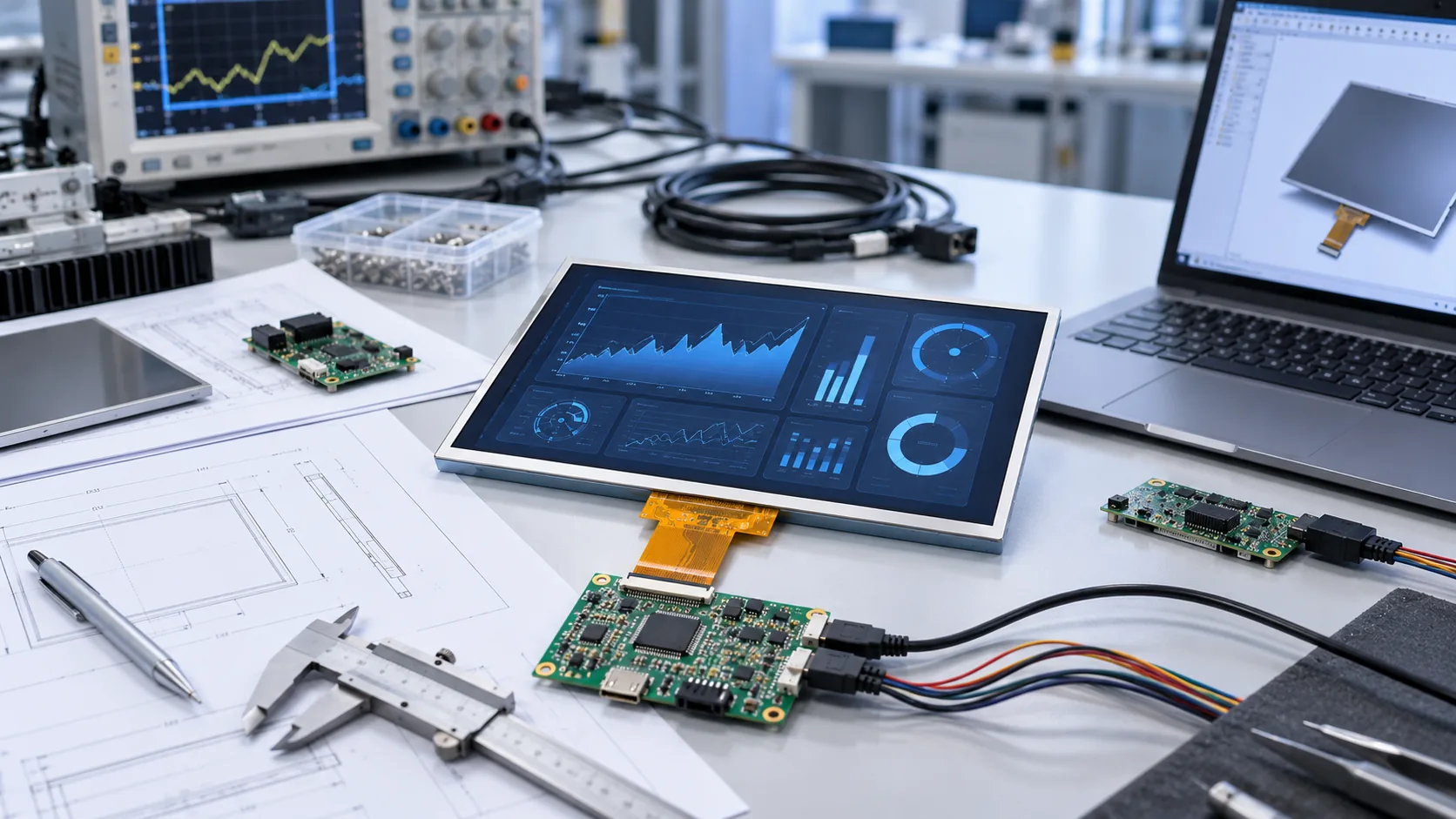
The first display enquiry does not need a complete specification. It does need enough evidence to avoid a false match. A diagonal size and a resolution are useful starting points, but they do not prove that a module fits the enclosure, connects to the host, is readable through the final front stack or behaves correctly in the application environment.
1. Define the equipment and display job
State what the display needs to show and where it will be installed. Include the device type, user distance, information density, orientation, whether the unit is handheld or fixed, and whether the user operates it with bare fingers, gloves, a stylus or no touch at all. This context helps determine which questions matter before a module is shortlisted.
- Application and device type
- Target display area, orientation and preferred aspect ratio
- Content to be shown: simple status, graphics, video, charts or a full HMI
- Whether an existing display is being replaced or a new device is being designed
2. Collect mechanical evidence early
For a replacement or enclosure-constrained project, begin with the current approved drawing. Record overall outline, active and viewing areas, thickness, bezel overlap, mounting holes or tabs, FPC exit direction, connector location, keep-out zones and the full front-stack construction. Photos are helpful, but they do not replace controlled dimensions and tolerances.
If the project has only a target display area, state the available opening and maximum stack depth rather than selecting a module based on nominal size. The obsolete LCD replacement guide explains why mechanical, FPC and electrical comparisons must remain separate checks.
3. Describe the host and electrical boundary
Identify the host processor or controller, the intended interface family, available supply rails, connector constraints and any existing timing or initialization information. For a current module, provide the exact model suffix, datasheet, pin definition and host schematic section if available. Pin count and connector pitch alone do not establish compatibility.
Useful inputs include interface type, logic-voltage context, cable or FPC route, backlight-control method, touch controller requirements and whether a driver board or adapter is being considered. The TFT LCD interface guide can help identify the questions for RGB, LVDS, MIPI and MCU host connections.
4. Set optical and environmental expectations
Describe the actual viewing environment: indoor light, bright ambient light, outdoor exposure, expected viewing angles and the front cover or touch stack. Record the required operating and storage conditions, duty cycle, condensation or cleaning exposure and any device-level shock, vibration or ESD requirements. These requirements belong to the equipment qualification plan and must be checked against the exact proposed configuration.
When touch, cover glass, anti-glare, anti-reflective treatment or optical bonding are relevant, name the use condition rather than assuming a finish. The sunlight-readable TFT LCD guide explains how brightness and front-stack reflection work together. For long-life equipment, also define the duty cycle, useful luminance endpoint and evidence requested in the industrial TFT backlight-lifetime guide.
5. Add the sampling and lifecycle context
State whether the project is at concept, prototype, replacement, pilot or production stage. Include the target quantity and schedule context, but keep the engineering question separate from purchasing assumptions. The sample review should freeze the exact model, drawing revision, electrical configuration and acceptance criteria before the product is released into a device program.
| Area | Useful evidence | If unknown |
|---|---|---|
| Application | Equipment type, display job, user and installation context | Describe the device and intended user workflow |
| Mechanical | Drawing, opening, depth, photos, mounting and FPC route | Provide available envelope and installed photos |
| Electrical | Host, interface, pinout, supply rails and timing information | Identify the processor or existing display model |
| Optical and touch | Viewing environment, lens/touch stack and input method | Describe light, gloves, water or stylus use |
| Validation | Sample stage, test conditions and approval responsibilities | State the project phase and open risks |
Use the checklist in a controlled sequence
Collect the available drawing, display label, host details, photos and environment information.
Do not label assumptions as requirements. List the questions that need confirmation before sampling.
Compare standard-module, replacement and customization routes against the actual constraints.
Use current documents and the approved sample for mechanical, electrical, optical and environmental checks.
Questions before an industrial TFT LCD enquiry
Why are size and resolution not enough to select an industrial TFT LCD?
Size and resolution do not define mechanical fit, FPC routing, connector and pin functions, host timing, backlight power, optical stack, touch behavior or environmental limits. Those constraints must also be compared before approval.
What if some display requirements are not known yet?
State which fields are unknown and start with the application, target display area, host platform, enclosure constraints and operating environment. The first engineering review can identify what must be confirmed before a sample is selected.
Can an existing display be used as the starting point?
Yes. Provide the exact model, photos, current drawing, datasheet, pinout and a working sample when possible. A replacement still requires a controlled comparison of mechanical, electrical, optical and environmental conditions.
When should the final drawing and datasheet be requested?
Request the current approved drawing, datasheet and pinout before design lock and validate the exact sample configuration against the host system and enclosure.
When you are ready, browse the industrial TFT module catalogue, review the custom TFT engineering options or send the material you already have for a project review.