Start with the finished front stack
Evaluate the cover lens and its surface treatment together with the display, not as a later cosmetic choice.
Outdoor readability is a system outcome: brightness, reflection, cover glass, bonding and UI design interact.
Match the luminance, front-surface reflection and viewing geometry to the equipment's real ambient-light conditions. Read the sunlight-readable TFT LCD guide for a practical comparison of brightness, air gaps, optical bonding, AG and AR. Start with high-brightness TFT LCD requirements, then assess the complete front stack.
A high-brightness module alone does not establish sunlight readability. Validate the finished display stack—cover lens, bonding, reflection, UI contrast and installation angle—under the target ambient light.
Evaluate the cover lens and its surface treatment together with the display, not as a later cosmetic choice.
Brightness, AG, AR and optical bonding address different parts of the optical system and should be reviewed separately.
Viewing angle, enclosure depth and UI contrast affect the operator result. Review outdoor-equipment considerations; where the use environment also has temperature exposure, include wide-temperature requirements.






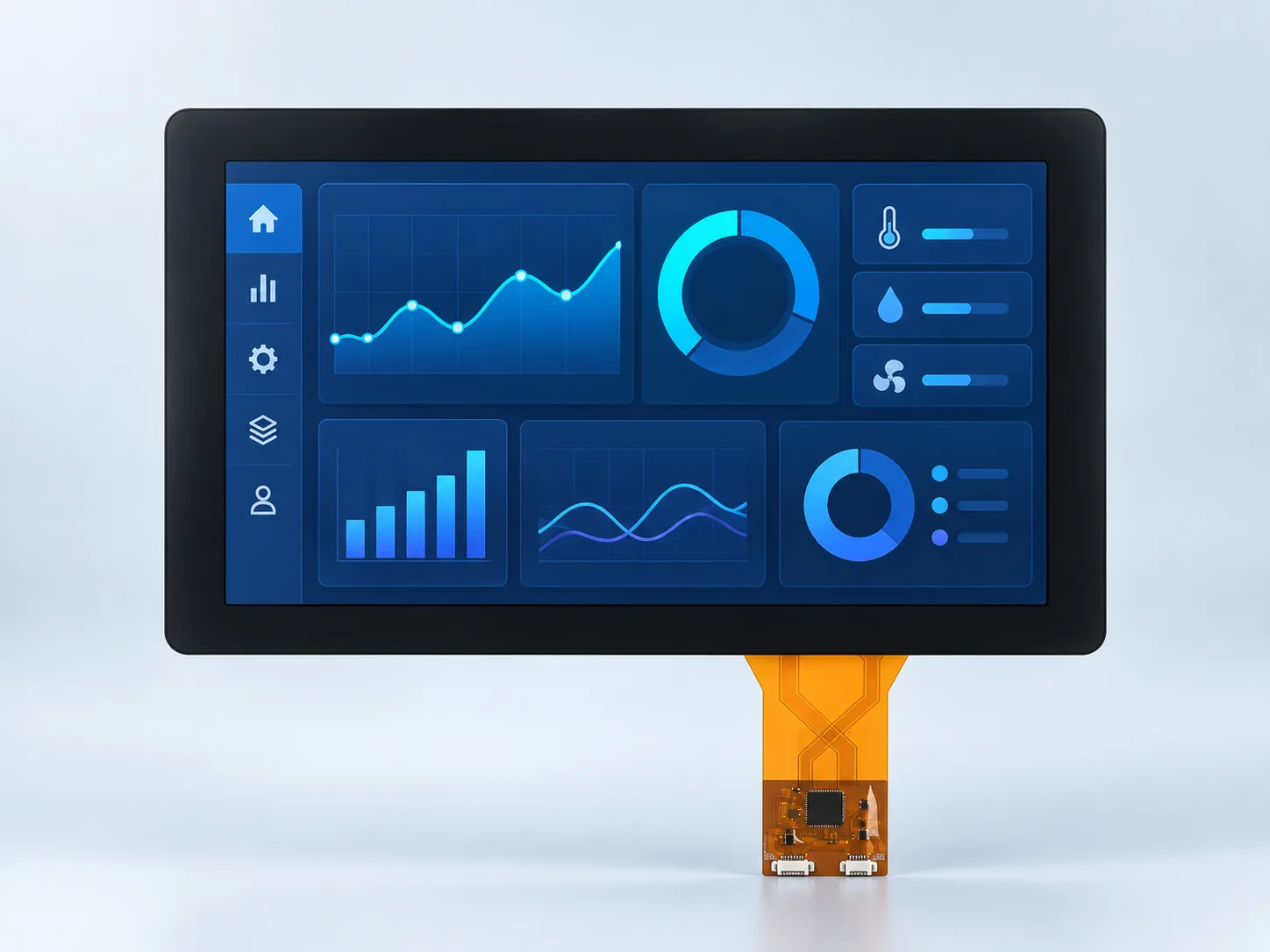



Define the installed viewing result first, then divide the work into emitted light, reflection control, front-stack construction and environmental validation. This prevents one “sunlight-readable” label from hiding different optical and thermal risks.
State whether the equipment sees indoor glare, bright shade, indirect daylight or direct sun. Include the normal operator position and display angle because reflections are directional.
Compare available modules against optical losses, power and heat rather than selecting the largest number. Use the outdoor luminance comparison to structure this decision.
AG diffuses strong reflections, AR reduces reflected intensity and optical bonding removes an internal air gap. Their effects are different; compare them in the front-stack guide.
Cover thickness, printed borders, coatings, touch construction and bonding all affect the optical path. Confirm the exact stack rather than assuming a bare-panel result will carry through the enclosure.
Bright backlights and absorbed sunlight add heat. Evaluate the display, driver and sealed enclosure together using the high-brightness thermal checklist.
Use the intended cover stack, dimming level, enclosure and UI. Observe readability from required angles and document the light and temperature conditions for sample comparison.
No. A high-brightness module provides more emitted light, but sunlight readability describes the installed viewing result. Reflection, cover glass, touch, bonding, UI contrast and installation geometry must also be evaluated.
No. Bonding can remove an internal air gap and may improve optical and mechanical behavior, but it also changes materials, tolerances, process and repair considerations. Review the optical bonding design guide against the actual front stack.
They address different reflection behavior and may be used separately or together depending on the lens and viewing condition. Confirm coating location, surface appearance, cleanability and optical result on a representative sample.
Send the ambient-light condition, display orientation, viewing distance and angle, target size and interface, enclosure and cover concept, temperature range, touch requirement, power limits and expected duty cycle.
Use the engineering review to combine optical, mechanical and electrical requirements before sampling.