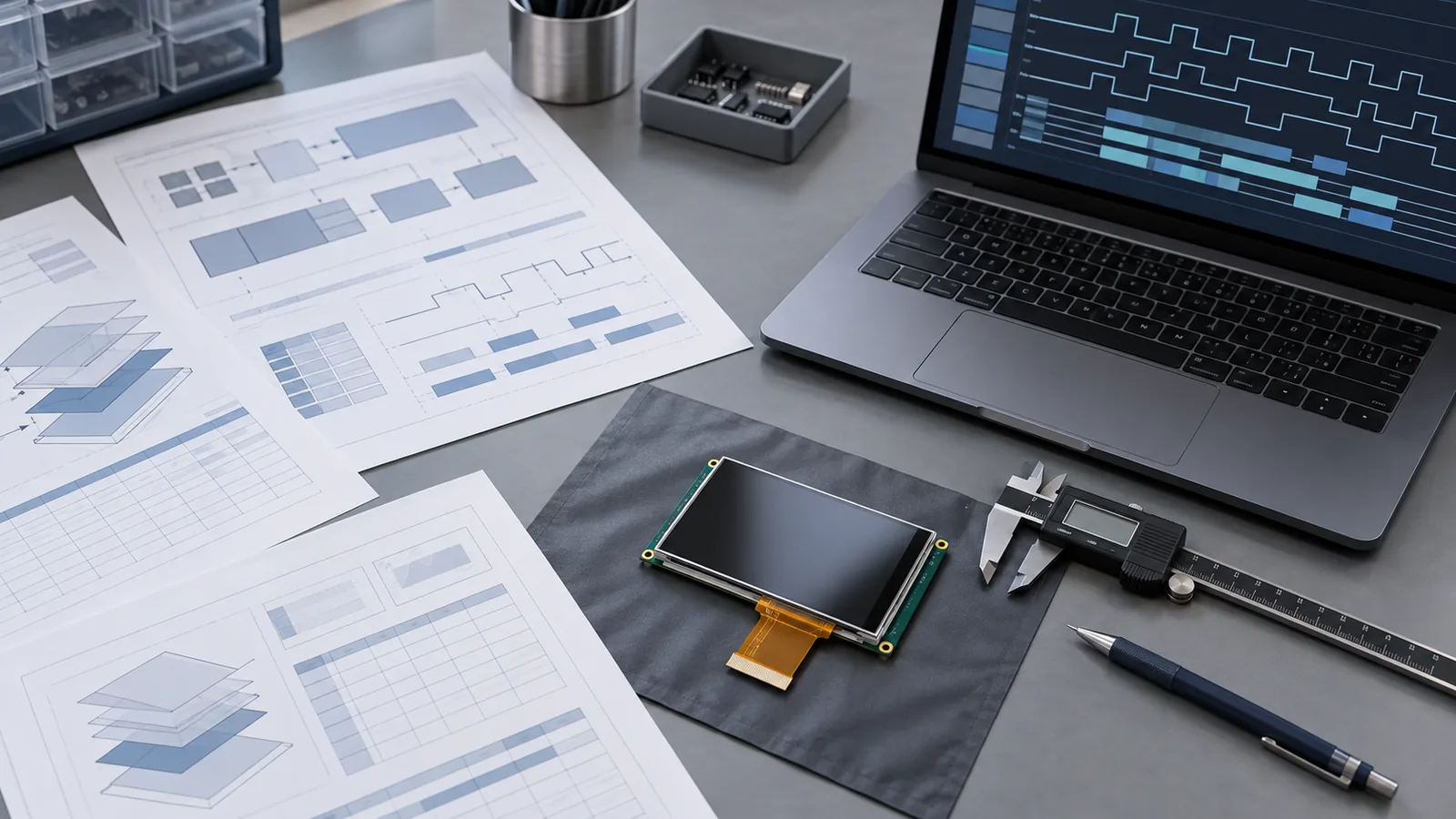
Two TFT LCD modules can look the same on a product page and behave differently in your product. The page gives a size, a resolution and a brightness. The controlled datasheet tells you how that brightness was measured, what the interface timing allows, how the backlight is wired and what the manufacturer tested. This guide walks through a TFT LCD datasheet section by section and shows what each part is for, what is commonly misread and what to confirm before you order samples.
It pairs with the requirements checklist, which lists what to send a supplier, and the sample validation checklist, which covers what to test afterwards. This article covers the step in between: understanding what the document says.
Summary spec, datasheet, drawing and sample
Four different things are often called “the spec.” Keep them apart:
- Summary specification. The headline table on a product page or in a catalog. It helps build a shortlist and is not a controlled document.
- Controlled datasheet. The model-specific document with revision history, ratings, electrical and timing tables, backlight data, optical test conditions, reliability tests and pin assignment.
- Approved drawing. The controlled mechanical document for outline, active area, tolerances, FPC exit and mounting.
- Physical sample. The only thing that shows how the module behaves with your host, your front stack and your enclosure.
TFTWorks states this separation on its own pages: product pages carry summary specifications only, and the current datasheet and drawing should be requested before design-in. You can request them through the datasheet request form.
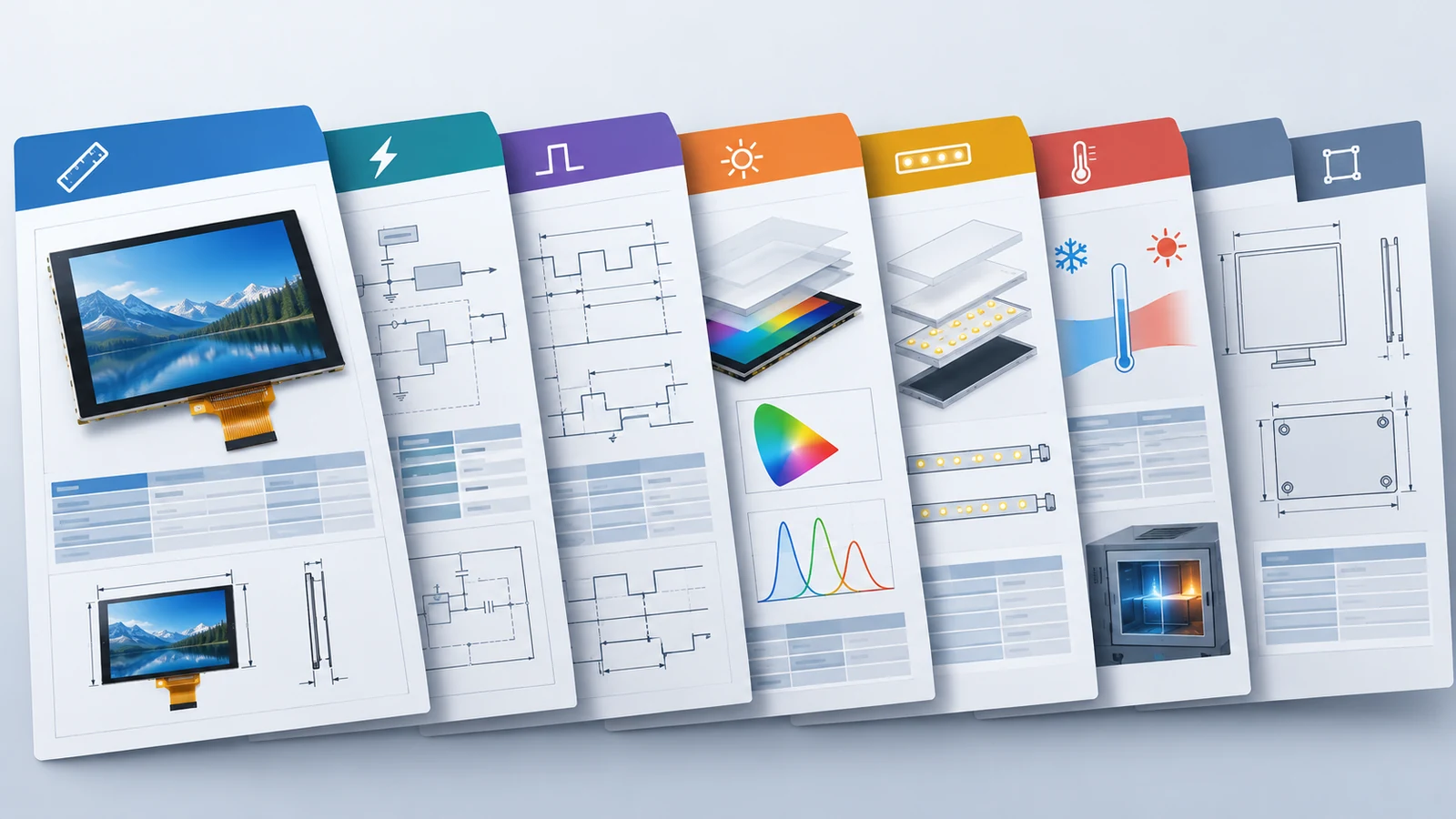
A datasheet map
| Section | What it tells you | Common mistake |
|---|---|---|
| Revision history | What changed and when | Designing from an old revision |
| General specifications | Size, resolution, active area, outline, weight, interface, backlight type | Treating a similar part as an identical one |
| Absolute maximum ratings | Limits that cause damage if exceeded | Using them as operating limits |
| Electrical characteristics | Supply voltages, currents, logic levels, power sequencing | Ignoring inrush and sequencing |
| Interface timing and pin assignment | Allowed clock, blanking, signal mapping and pin function | Assuming a matching connector means a matching interface |
| Backlight characteristics | LED string layout, voltage, current, lifetime definition | Comparing lifetime hours with different definitions |
| Optical characteristics | Luminance, uniformity, contrast, viewing angle, response, color | Reading a number without its test condition |
| Reliability tests | Which environmental tests were run and the pass criteria | Reading a test table as a guarantee for any use |
| Mechanical drawing | Outline, tolerances, FPC and connector, mounting | Using a reference image instead of the approved drawing |
| Handling precautions | ESD, polarizer, bending, pressure, static images | Skipping the last pages |
Revision and model suffix
Start with the front page, not the tables. Confirm the exact model name, suffix and revision. A suffix can mean a different touch, bonding, FPC or temperature variant. In the published TFTWorks range, for example, DS-T101HIEWA-01CP is the bonded PCAP version of the 10.1-inch 1280×800 module, which is listed separately from the no-touch DS-T101HIEWA-01 with a different luminance. Freeze the model, suffix and revision in your bill of materials, and ask how changes are communicated.
General and mechanical data
Use the general table to check the module against your enclosure and host, then use the approved drawing for tolerances. Look at active area, outline, thickness, FPC exit direction and mounting features. Derived numbers help sanity checks. For example, a 12.1-inch 1280×800 module with a listed active area of 261.12 × 163.20 mm has a pixel pitch of about 0.204 mm (261.12 ÷ 1280), or roughly 124 pixels per inch, which is useful when you size text and touch targets.
Do not size the enclosure from the active area alone. The outline, bezel width, FPC bend radius and connector position decide the real space. See the FPC and pinout customization guide if the tail or pinout does not fit.
Absolute maximum ratings vs operating conditions
Absolute maximum ratings are the limits beyond which damage can occur. They are not conditions to design to, and the module is not expected to meet its specification at those values. Design inside the recommended operating conditions with margin for supply tolerance, ripple, temperature and ESD events. Check storage temperature separately: it is the range the module can be kept in without power and it can differ from the operating range.
Electrical, interface and timing
This is the part that decides whether the host can drive the module. Check four things:
- Supply rails and current. Voltage range, typical and maximum current, and any inrush at power-up.
- Power sequencing. The required order and timing of logic power, signals and backlight enable, and what happens at reset.
- Interface timing. Pixel clock range and the allowed horizontal and vertical blanking, with minimum, typical and maximum values. Use the RGB timing guide to calculate your clock.
- Pin assignment and mapping. Pin function, color-bit order, lane or pair order, polarity and unused-pin handling. The TFT LCD interface guide, LVDS cable guide and MIPI DSI lane guide explain the host side.
If the image is missing or shifted at bring-up, the interface troubleshooting guide turns these tables into a symptom-led workflow.
Backlight characteristics
The backlight table usually lists the LED string layout, the forward voltage, the drive current and the power. It decides what your driver must supply and how the display will heat the enclosure. Check these items:
- Where the driver lives. On the module, on a controller board or on your host board. If the page does not say, ask.
- The lifetime definition. L50 or L70, the test temperature and the drive current. See the backlight lifetime guide.
- Dimming behavior. The dimming method and range the backlight tolerates. See the backlight dimming guide.
- Heat. Backlight power at the target luminance feeds the thermal plan; see the thermal trade-offs guide.
Optical characteristics and their test conditions
Optical numbers are the most misread part of a datasheet because each one hides a condition. Read the conditions in the table notes, not only the value.
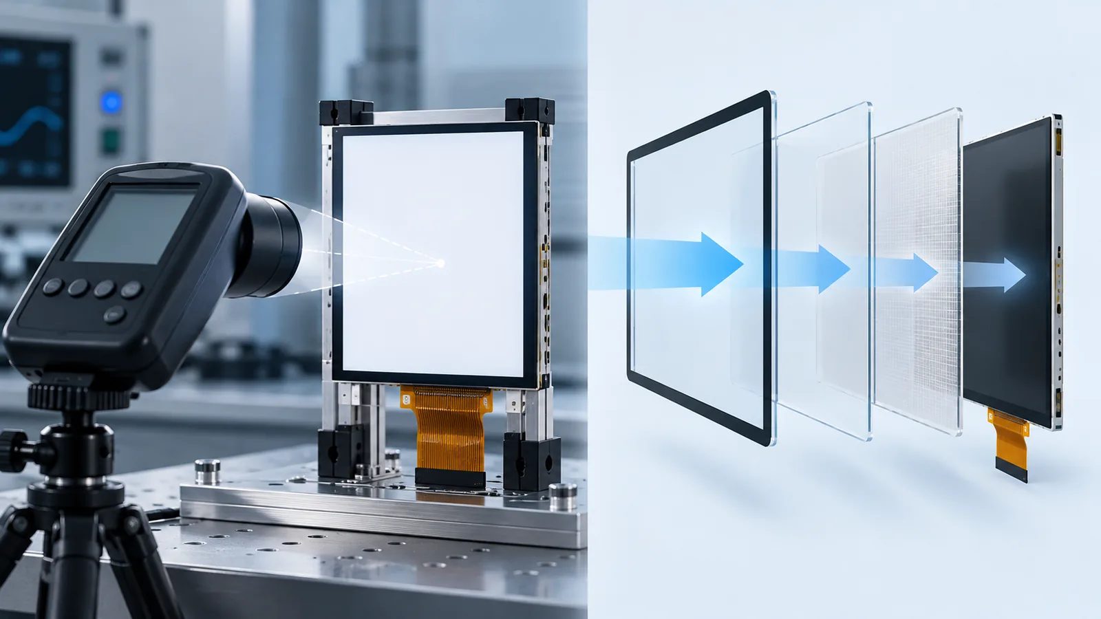
| Parameter | Condition behind the number | What to confirm in your product |
|---|---|---|
| Luminance | Usually measured at the center of the active area, at a stated temperature and backlight current, on the bare module; may be typical or minimum | Luminance through your cover glass, touch stack and bonding, at your temperature and backlight setting |
| Uniformity | Measured at several points with a stated method | Visible variation on your real screens, especially dark ones |
| Contrast ratio | Usually measured in a dark room, on axis | Contrast under your ambient light and reflections |
| Viewing angle | Often defined by a contrast threshold, not by an unchanged image | Color and brightness shift from the real viewing positions |
| Response time | Measured between stated gray levels at a stated temperature | Motion behavior at the cold end of your range |
| Color gamut | Stated against a reference and measurement setup | Whether your UI colors need accurate reproduction |
A few reading rules save time. Check whether luminance is typical or minimum; if readability is critical, plan from the minimum or from your own measurement. Check whether the number includes a touch panel or cover. Read the viewing-angle definition before you compare two parts, and see the IPS vs TN guide for how panel type changes off-axis behavior. For brightness targets, use the 800 vs 1000 vs 1200 nit guide.
Environmental and reliability tables
Reliability tables list the tests run, such as high and low temperature storage and operation, humidity, thermal shock, vibration and ESD, with test conditions and pass criteria. Read them as type-test evidence under stated conditions, not as a guarantee for any use. Compare each test with your own profile: the temperature extremes, the duration, whether the module was powered, and how the module was mounted. If your product needs a condition that is not listed, ask whether it was tested or plan to test it yourself. The wide-temperature selection guide explains how to separate storage, operating and cold-start requirements.
Handling precautions
The last pages often hold the details that cause field problems: ESD handling, polarizer scratch and pressure limits, FPC bend radius, mounting torque, and guidance on displaying static images for long periods. Read them before you write assembly instructions, and carry the relevant items into your own production documents.
Worked example: a published summary table
Take the summary table for the DS-T121BIHA-01 12.1-inch module. It lists a 1280×800 IPS panel, luminance of 1000 cd/m², an 8-bit LVDS 40-pin interface, no touch panel, an active area of 261.12 × 163.20 mm, an outline of 277.70 × 180.60 × 6.00 mm and an operating and storage temperature of −20 to +70 °C. That is enough for a shortlist. It is not enough for design-in, and the page says so.
| Item | On the summary page | Question to ask before design-in |
|---|---|---|
| Luminance | 1000 cd/m², stated as a module specification | Typical or minimum? Measured at what temperature and backlight current? What is the value through your cover and touch stack? |
| Interface | 8-bit LVDS, 40-pin | Pinout, mapping, timing limits and connector. A matching pin count does not prove compatibility |
| Temperature | −20 to +70 °C operating and storage | Cold-start time and heat inside a sun-loaded enclosure; the rating does not answer these |
| Driver IC | Not confirmed on the page | Confirm in the current datasheet |
| Contrast, response, numeric viewing angle | Not listed | Request them with their test conditions |
| Backlight type, current and power | Not listed | Needed for the driver and the thermal budget |
| Pin assignment | Not listed | Needed before you design the host board or cable |
Every “not listed” row is a question, not a defect. Send the questions with your host details through the datasheet and sample review request. The same approach works for any module in the industrial TFT range, and the standard module catalog is a useful shortlist reference, not a controlled datasheet.
Red flags and a pre-sample checklist
Red flags
- No revision number or date on the datasheet.
- Optical values with no stated test condition.
- “TBD” or blank fields for the driver IC, backlight current or pinout.
- A pinout drawn only as an image, with no table.
- A lifetime figure with no end-of-life criterion.
- A reliability table with no pass criteria.
Ten checks before you request a sample
- Exact model, suffix and revision are frozen.
- The approved drawing matches your enclosure and FPC route.
- Supply rails, current and sequencing are compatible with your power design.
- Interface timing and pin assignment match your host output.
- The backlight driver location and drive method are known.
- Luminance is understood as typical or minimum, with its test condition.
- Your front stack loss is estimated or measured.
- Operating and storage ranges cover your enclosure profile.
- Handling precautions are carried into your assembly documents.
- Acceptance criteria for the sample are written before it arrives.
TFT LCD datasheet FAQ
What is the difference between a TFT LCD datasheet and a specification summary?
A specification summary lists headline values such as size, resolution, luminance and interface to help build a shortlist. A controlled datasheet is the model-specific document with revision history, absolute ratings, electrical and timing tables, backlight data, optical test conditions, reliability tests and pin assignment. Design-in should use the controlled datasheet and the approved drawing.
Should I design to typical or minimum luminance?
Check which value the datasheet lists and under what conditions. Typical values describe a central expectation under stated test conditions, while a minimum value gives a floor. If readability is critical, plan from the minimum or from your own measurements, then account for the cover glass, touch stack, temperature and backlight aging.
Does the viewing angle on a datasheet mean the image looks the same at that angle?
Not necessarily. Datasheets commonly define viewing angle by a contrast threshold, so the image can still shift in color and brightness well inside the stated angle. Check the definition, then judge your own screens from the real viewing positions.
Is the storage temperature the same as the operating temperature?
No. Operating temperature is the range in which the module is meant to work, and storage temperature is the range it can be kept without power. They can differ, and the operating range must be met inside your enclosure, including heat from the backlight and from sun load.
Technical references
- Crystalfontz — Demystifying TFT LCD display specifications: a general buyer's introduction to resolution, refresh rate, response time, panel type, brightness, contrast and color gamut.
Request the Current Datasheet and Drawing
Send the model you are reviewing, your host interface and the questions the summary table leaves open. TFTWorks will review the request against the exact configuration and the current documents.
Request a Datasheet Download the RFQ checklist (PDF)
How to send drawings or UI screenshots
The project-review form accepts text details, not file uploads. Send your initial requirements there, or attach your files directly by email or WhatsApp. Include the reference model, your company and the project context so the files can be matched to your enquiry. Do not send confidential files without agreeing the sharing terms.
Continue the engineering review
Publisher and scope. Published by TFTWorks, operated by Guangdong Dexing Microelectronics Co., Ltd. Datasheet structure and terminology vary by supplier and model, and values quoted from product pages are summary references. Confirm every value against the current controlled datasheet and approved drawing before design-in.