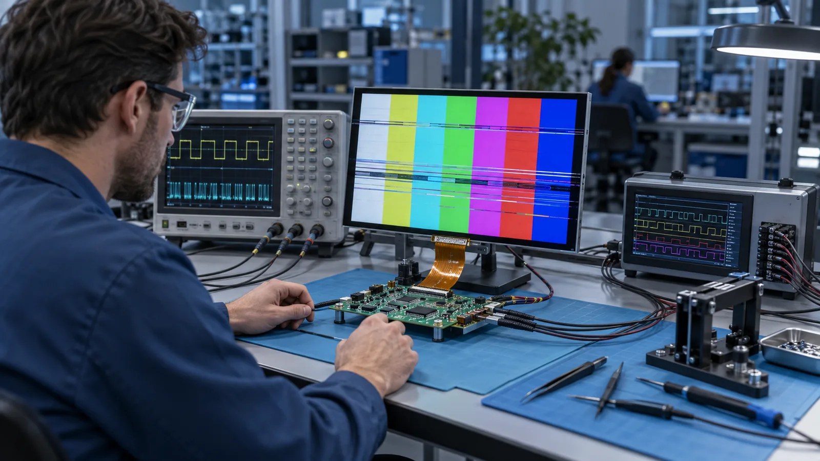
A blank or corrupted TFT does not automatically mean that the LCD is defective. The same symptom can come from a missing power rail, reversed FPC, wrong reset sequence, incompatible interface, incorrect pixel timing, lane mapping, initialization code, memory underflow or a marginal physical link. Replacing the panel before locating the failure boundary often wastes the best evidence.
Keep one known configuration whenever possible: known host firmware, known cable and known display. Change one variable at a time and record each result. If the interface family itself is uncertain, use the TFT LCD interface guide before troubleshooting signals.
Before connecting probes or swapping modules
- Confirm logic, analog and backlight voltage limits from the current module datasheet.
- Power down before inserting or removing an FPC unless the connector and system are designed for hot-plug operation.
- Verify connector contact side, pin 1 and locking mechanism.
- Use ESD controls and avoid shorting fine-pitch pins with a probe tip.
- For high-speed differential links, use an appropriate probe, fixture and measurement point; unsuitable probing can create a fault.
Start from the visible symptom
| Symptom | First areas to check |
|---|---|
| No backlight and no image | Input power, backlight supply/enable, connector orientation and protection devices. |
| Backlight on, screen black | Panel rails, reset, display-enable, host output, initialization and active-data timing. |
| White or uniform bright screen | Panel drive state, missing image stream, DE/sync, DSI initialization or bus communication. |
| Wrong colors | RGB order, bit mapping, pixel format, LVDS mapping or DSI packet format. |
| Shifted, clipped or repeated image | Active width/height, porches, line timing, address window or dual-channel mapping. |
| Rolling or unstable frame | Frame timing, VSYNC/TE handling, pixel clock and buffer switching. |
| Sparkles, random lines or intermittent pixels | Clock edge, setup/hold margin, differential-link quality, cable/connector and power noise. |
| Flicker or brightness pulsing | Backlight PWM, power ripple, grounding, frame updates and display-enable behavior. |
| Works only after reboot or when warm | Power sequence, reset delay, initialization timing, oscillator/PLL margin and connector variation. |
A repeatable eight-step troubleshooting workflow
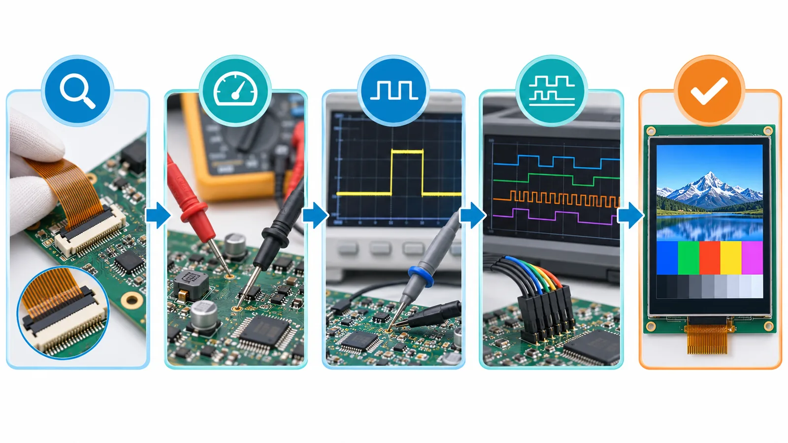
- Record the exact configuration. Note module suffix, host board revision, cable/FPC revision, firmware build and the conditions that trigger the fault.
- Inspect the physical connection. Check pin 1, contact side, connector lock, bent contacts, contamination, insertion depth, cable damage and strain.
- Measure every power rail. Check at the module connector during startup and operation, not only at the regulator.
- Verify reset and mode pins. Confirm voltage levels, pulse duration and timing relative to power and clocks.
- Prove host activity. Check that clock, sync, low-power signaling, commands or write strobes reach the connector.
- Compare the complete configuration. Cross-reference pinout, voltage, timing, mapping, lane/bus width, mode and initialization.
- Use diagnostic patterns. Solid colors, ramps, checkerboards, single-pixel lines and motion separate mapping, timing and link faults.
- Test margins and corners. Repeat at required voltage, temperature, workload, cable position and nearby switching-load conditions.
Power, reset and backlight checks
Measure the voltage at the display connector with the module attached. A regulator can look correct with no load and collapse during panel startup. Check ramp order, rise time, ripple and discharge between cycles where the datasheet specifies them. Confirm that reset is asserted and released only after the required rails are valid.
The backlight driver has its own input, LED output, enable and often PWM dimming. A backlight fault can hide a working image, and a PWM or grounding fault can appear as display flicker. View the LCD under external light if appropriate to determine whether image data exists without illumination.
Some panels also need standby, display-enable, I²C or SPI register configuration. Do not assume that an RGB, LVDS or MIPI data path removes every control requirement.
Pinout, connector and FPC
Match every pin by signal name and electrical function. The same pitch and pin count do not establish compatibility. Connector contact side, top/bottom contact orientation and pin numbering can reverse an otherwise similar cable. Check power, ground, no-connect and backlight pins before attaching an alternate module.
Use continuity measurements on an unpowered assembly when a cable or adapter is suspect. Inspect for partial insertion and pins that make contact only when the harness is pressed. If the project changes connector position or mapping, freeze it through a controlled drawing using the custom TFT LCD FPC checklist.
Parallel RGB interface checks
- Confirm I/O voltage, RGB bus width and every color-bit position.
- Measure PCLK frequency and determine the actual panel sampling edge.
- Verify DE, HSYNC and VSYNC polarity and whether the panel uses DE-only or sync timing.
- Compare active width/height, sync widths and front/back porches against the panel ranges.
- Check setup/hold margin, ringing, ground reference and host drive strength.
- Monitor LCD-controller DMA or FIFO underflow during full system load.
A shifted or rolling picture usually points toward timing; recognizable content with wrong colors usually points toward mapping or pixel format. The RGB TFT LCD timing guide provides the clock and blanking formulas.
LVDS interface checks
- Confirm single- or dual-channel mode and the exact pixel mapping convention.
- Verify clock/data pair order and polarity at both connectors.
- Check pixel-clock range, color depth and odd/even pixel assignment where applicable.
- Inspect the cable for correct differential construction, pair matching, shield/ground plan and strain relief.
- Check connector transitions, receiver termination and the complete signal path for discontinuities.
Wrong colors can be a mapping fault; a split or repeated image can indicate channel configuration; sparkles and temperature-sensitive faults can indicate link margin. Use the LVDS cable-length guide when the installed harness differs from the bench setup.
MIPI DSI interface checks
- Match lane count, lane mapping, pixel format, video/command mode and per-lane rate.
- Verify D-PHY timing, PLL/byte clock and continuous/non-continuous clock behavior.
- Capture reset, sleep-out, display-on and vendor-specific initialization commands.
- Check low-power to high-speed transitions and host timeout/error status.
- For command mode, verify address windows, update commands and tearing-effect synchronization.
- Use measurement hardware suitable for the D-PHY rate and loading limits.
A correct connector and lane count do not guarantee protocol compatibility. Review the MIPI DSI lane-selection workflow before changing PHY rates or adding lanes.
MCU and SPI interface checks
- Confirm the controller IC and use the initialization table for the exact module revision.
- Verify CS, D/C, reset, read/write strobes, bus width, SPI mode and bit order.
- Read the controller ID or status where the design supports it.
- Start at a conservative supported clock, then increase speed while watching signal quality and write timing.
- Check column/page address windows, orientation, color order and bytes-per-pixel settings.
- Separate a communication failure from a backlight or panel-power failure.
A display that accepts commands but shows a displaced image often has an address-window, orientation or pixel-format mismatch. A bus that fails only at higher speed may need timing, routing, drive-strength or level-shifting review.
What to measure and capture
| Evidence | What it can establish |
|---|---|
| Power-rail startup capture | Rail order, ramp, reset relationship, droop and ripple. |
| Connector photos and pinout | Orientation, insertion, cable revision and mapping. |
| Logic-analyzer capture | Low-speed commands, SPI/MCU transactions and reset sequence. |
| Oscilloscope timing capture | RGB clock/sync relationship, strobes, ripple and selected link behavior. |
| Host error/status registers | DSI timeouts, FIFO underflow, protocol or PHY events where supported. |
| Diagnostic test-pattern photos | Color mapping, bit errors, geometry and intermittent corruption. |
| A/B substitution log | Whether the fault follows the panel, cable, host, firmware or environment. |
Intermittent and environment-dependent faults
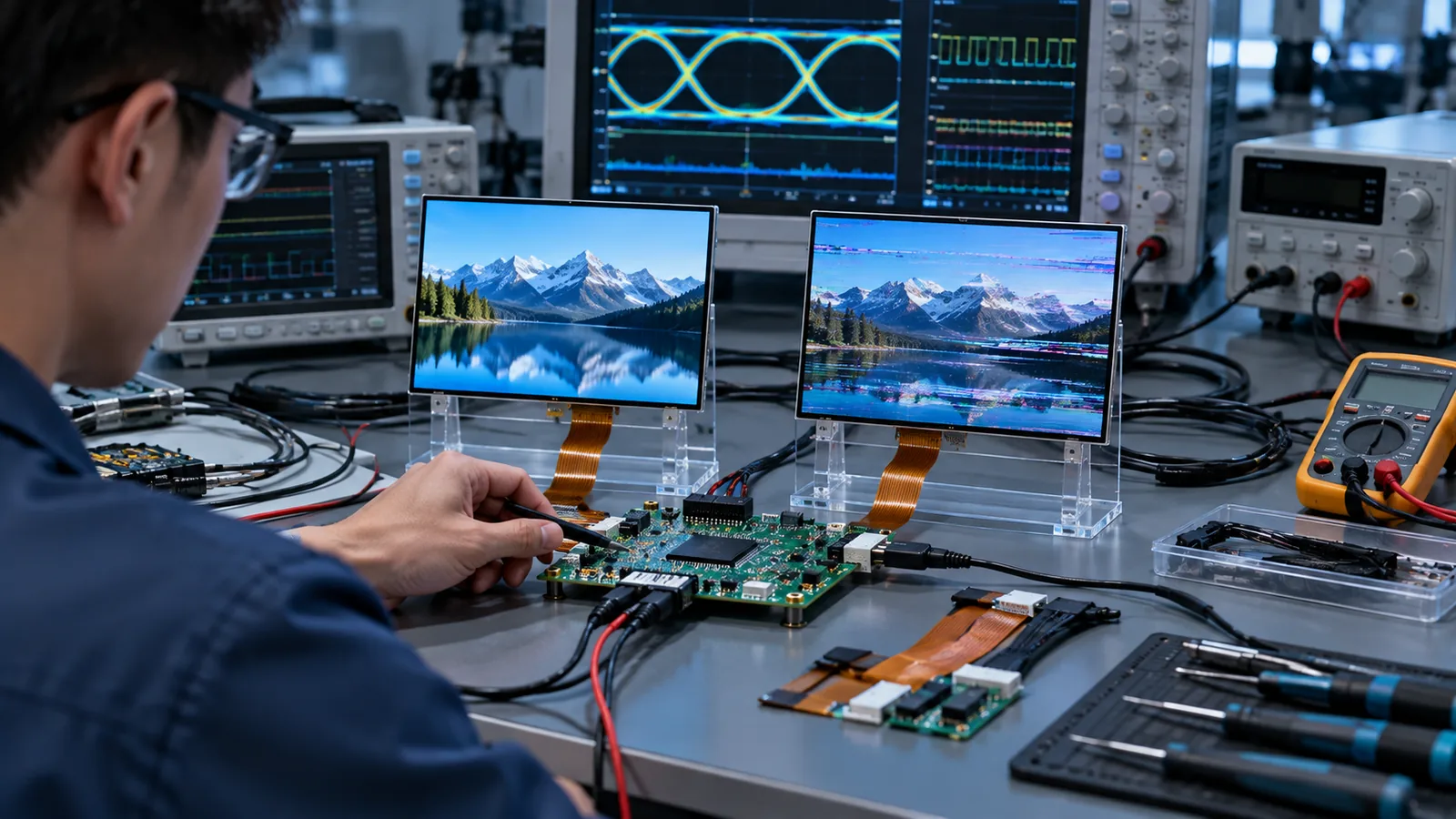
Intermittent failures need a trigger matrix. Record whether the symptom follows cold start, warm operation, vibration, cable movement, radio transmission, motor switching, backlight PWM, CPU load or a particular screen update. Correlation narrows the mechanism more effectively than repeated component replacement.
Use the final enclosure and production cable when checking EMC and thermal behavior. Ground paths, shield termination, mounting pressure and cable routing can change after the open-bench prototype. Test more than one sample when deciding whether a result represents design margin or a single-unit condition.
When an alternate panel does not work
A similar-size replacement may differ in outline, active area, power, pinout, timing, mapping, controller, initialization and optical stack. Compare controlled documents field by field. Do not modify firmware randomly until the mechanical and electrical compatibility table is complete. For lifecycle projects, follow the obsolete industrial TFT LCD replacement workflow.
What to send for engineering support
- Exact TFT model and full suffix, datasheet and drawing.
- Host processor, bridge or controller-board part number.
- Connector and cable/FPC drawings with pinout.
- Power tree, reset sequence and measured startup waveforms.
- Interface configuration: timing, lane/bus width, mapping, pixel format and clock.
- Initialization code or transaction capture.
- Clear symptom photos/video and the conditions that reproduce the fault.
- Results of controlled A/B tests using known panels, cables, boards or firmware.
Mark unknown fields as unknown. A precise partial record is more useful than assumed values.
Technical references
- NXP — i.MX RT eLCDIF RGB Mode Use Case (AN12302): RGB timing structure and controller configuration.
- Texas Instruments — LVDS Owner’s Manual: LVDS topology, termination and interconnect behavior.
- MIPI Alliance — Display Serial Interface: official DSI protocol and display-link overview.
- NXP — i.MX 8/RT MIPI DSI/CSI-2 (AN13573): MIPI DSI architecture, modes and host configuration context.