Short Answer
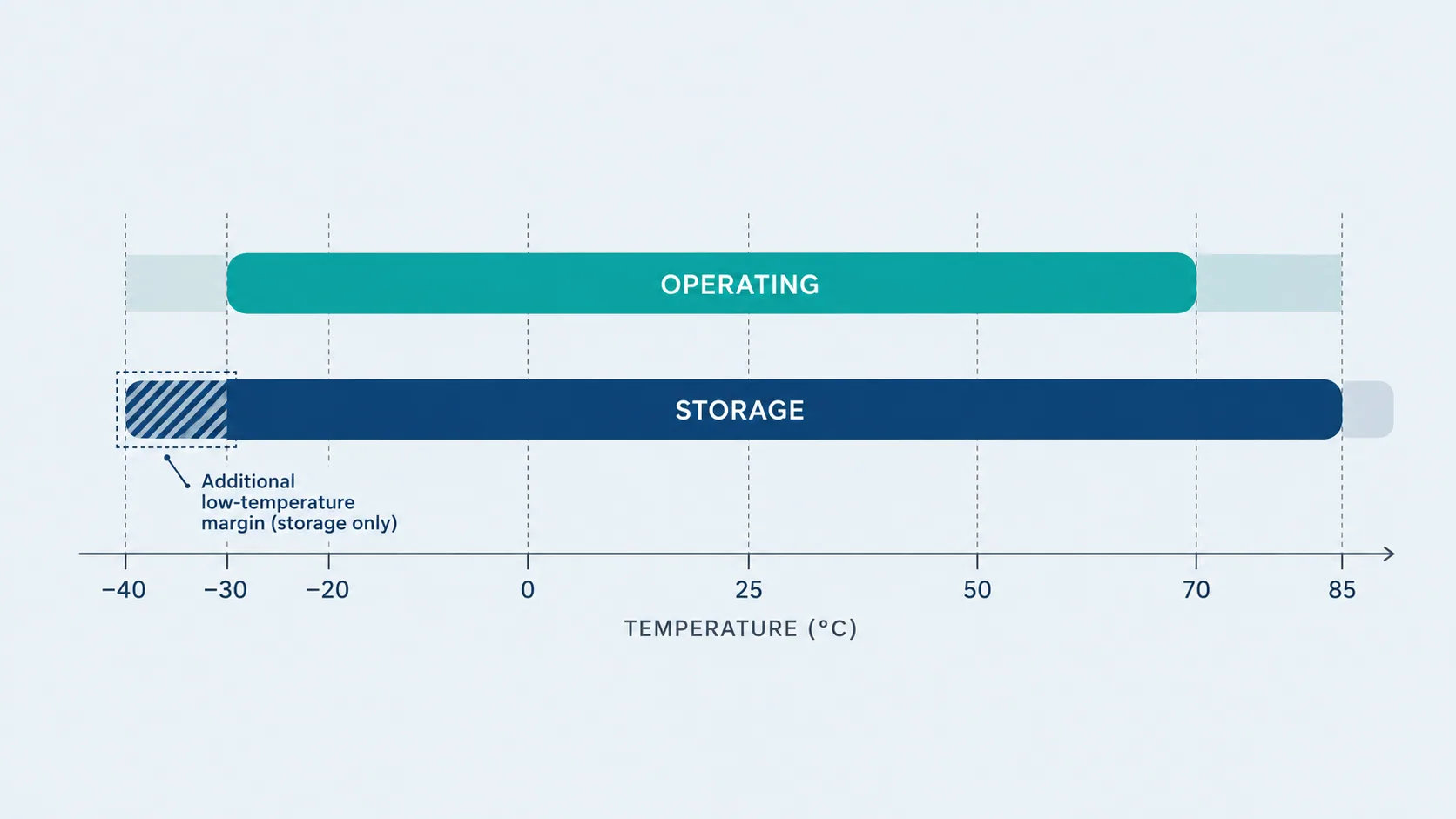
Compare four things, in this order: the storage range (materials, and often the tightest limit), the operating range (liquid crystal and electronics, at a measurement point on the module rather than in your cabinet), the cold-start requirement (frequently not specified at all, and not the same as the operating minimum), and the hot-end margin left after self-heating from a high-brightness backlight and any solar load. A module quoted at −30 to 85 °C can still fail a −40 °C unheated shipment, and a module with plenty of headroom on paper can run out of it behind a sealed black enclosure in direct sun. Decide the four numbers for your equipment first, then shortlist.
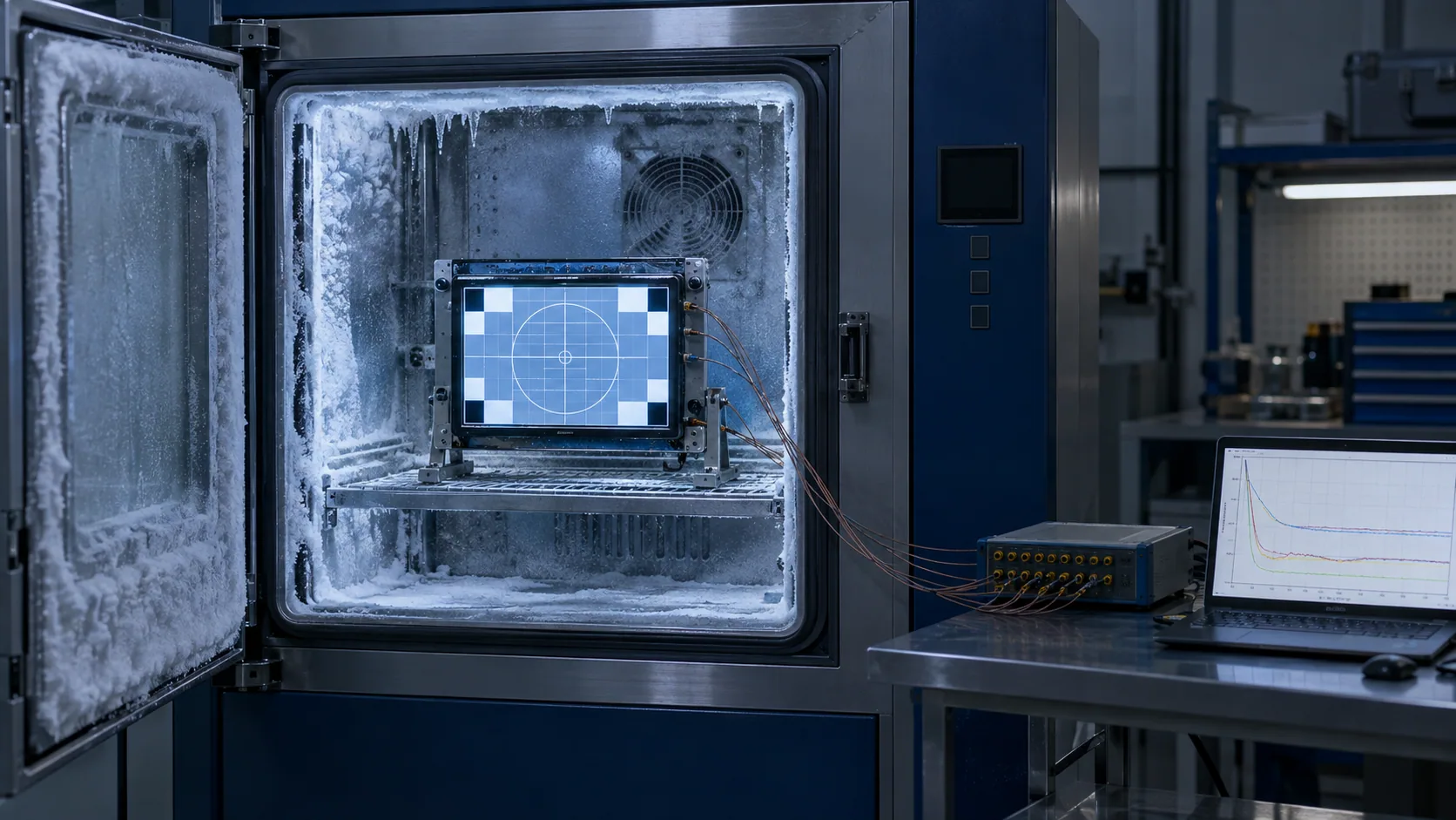
Four Temperatures, Not One
Most wide-temperature enquiries arrive as a single line: "we need −30 °C". That sentence hides a decision that has to be made four times.
- Storage, unpowered. What the module sees in a container, on a pallet in an unheated warehouse, or in a vehicle overnight. Nobody specifies this because nobody owns it — but it is often the coldest number in the whole programme.
- Non-operating in the field. An installed unit that is switched off, or a battery-powered unit that has discharged, still sits in the environment. It must survive, then work again.
- Operating. The range the display must remain readable and responsive through, at the worst case of ambient plus internal heating.
- Start-up. The temperature at which the equipment is expected to power on and show a usable screen within a defined time. This is the requirement most often missed and the one most likely to generate a field complaint.
Write all four down before comparing modules. A shortlist built from only the third one will be re-done later.
Read the Storage Range First
Operating and storage limits are set by different physics. The operating limits are dominated by the liquid crystal and the driving electronics. The storage limits are dominated by materials: polariser films, optical adhesives, the sealant around the cell, and the plastics in the backlight assembly. Because the mechanisms are different, there is no rule that the storage range must be wider.
This is easy to verify on real modules. Across our published wide-temperature module data, several parts list a storage range identical to the operating range, and one lists a storage minimum only 5 °C below the operating minimum. A display rated to operate at −30 °C is therefore not automatically cleared for unheated transit or storage below its published storage minimum.
| Model | Size / resolution | Luminance | Interface | Operating | Storage |
|---|---|---|---|---|---|
| DS-T035HLWSA-01 | 3.5″ 320×240 IPS | 900 cd/m² | RGB 24-bit, 54-pin | −30 to 85 °C | −30 to 85 °C |
| DS-T043BWSWA-02 | 4.3″ 800×480 IPS | 900 cd/m² | RGB 24-bit, 40-pin | −30 to 80 °C | −30 to 80 °C |
| DS-T050BWSWA-02 | 5.0″ 800×480 IPS | 1000 cd/m² | RGB 24-bit, 40-pin | −30 to 80 °C | −30 to 80 °C |
| DS-T070SWHWA-01 | 7.0″ 800×480 IPS | 1000 cd/m² | LVDS 6/8-bit, 20-pin | −30 to 85 °C | −35 to 85 °C |
| DS-T084BXJWA-02 | 8.4″ 1024×768 IPS | 1000 cd/m² | LVDS 8-bit, 20-pin VESA | −30 to 80 °C | −30 to 80 °C |
| DS-T101HIEWA-01 | 10.1″ 1280×800 IPS | 1000 cd/m² | LVDS 6/8-bit, 40-pin | −30 to +85 °C | −30 to +85 °C |
| DS-T104QXHA-03 | 10.4″ 1024×768 IPS | 850 cd/m² typ. | LVDS 6/8-bit, 30-pin | −30 to +80 °C | −30 to +80 °C |
If your logistics or field-storage case is colder than the storage minimum, the options are a different module, a controlled shipping and storage process you can actually enforce, or a documented deviation accepted by the customer. Silence is not one of them.
What Actually Happens at the Cold End
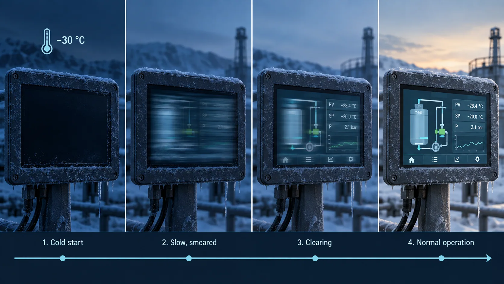
Liquid crystal is a fluid, and its viscosity climbs steeply as it cools. Three things follow from that, and they arrive in this order as the temperature drops.
Response time lengthens
Switching slows down. Motion smears, a scrolling list ghosts, and an animated trend line leaves a tail. Response time is very often specified only at 25 °C, so the datasheet is silent on exactly the condition you are worried about. If the interface has moving content, ask for the low-temperature figure or measure it.
Start-up becomes a separate question
Below a certain point the display can power up dark, patchy or unreadable and then recover over seconds to minutes as it self-heats. Whether that is acceptable depends entirely on the product: a machine that runs continuously does not care, a battery-powered field instrument that the user switches on in a −25 °C wind absolutely does. State a requirement in the form "readable within N seconds at T °C" and test it.
The backlight driver needs headroom
LED forward voltage rises as the junction cools, so a boost driver that is comfortable at 25 °C can drop out of regulation at −30 °C if it was sized without margin. The panel is fine; the driver is what dims or flickers. Check the compliance voltage of the driver against the string's worst-case cold forward voltage, not its typical value.
Two more cold-end items belong on the list and are usually forgotten: condensation on and inside a cold module when it is brought into humid air, and the loss of flexibility in the FPC and its adhesives, which makes a tight cable bend that survives 5,000 cycles at room temperature a different proposition at −30 °C.
What Actually Happens at the Hot End
The hot end is less dramatic and more expensive. Contrast falls and the image can wash toward grey as the liquid crystal approaches its upper limit; above the clearing point the effect is total, though a module will normally hit an electronic or material limit first. Polarisers and optical adhesives age faster, and hot-humid conditions are harder on them than dry heat.
The item that often decides the design is the backlight. LED luminous flux can fall as junction temperature rises, while elevated temperature can increase reliability stress. If the product must hold a luminance figure over its intended life, the relevant evidence is the lifetime test condition for the selected module and drive condition—not the temperature range alone. See the industrial TFT backlight lifetime guide.
The Datasheet Temperature Is Not Your Ambient
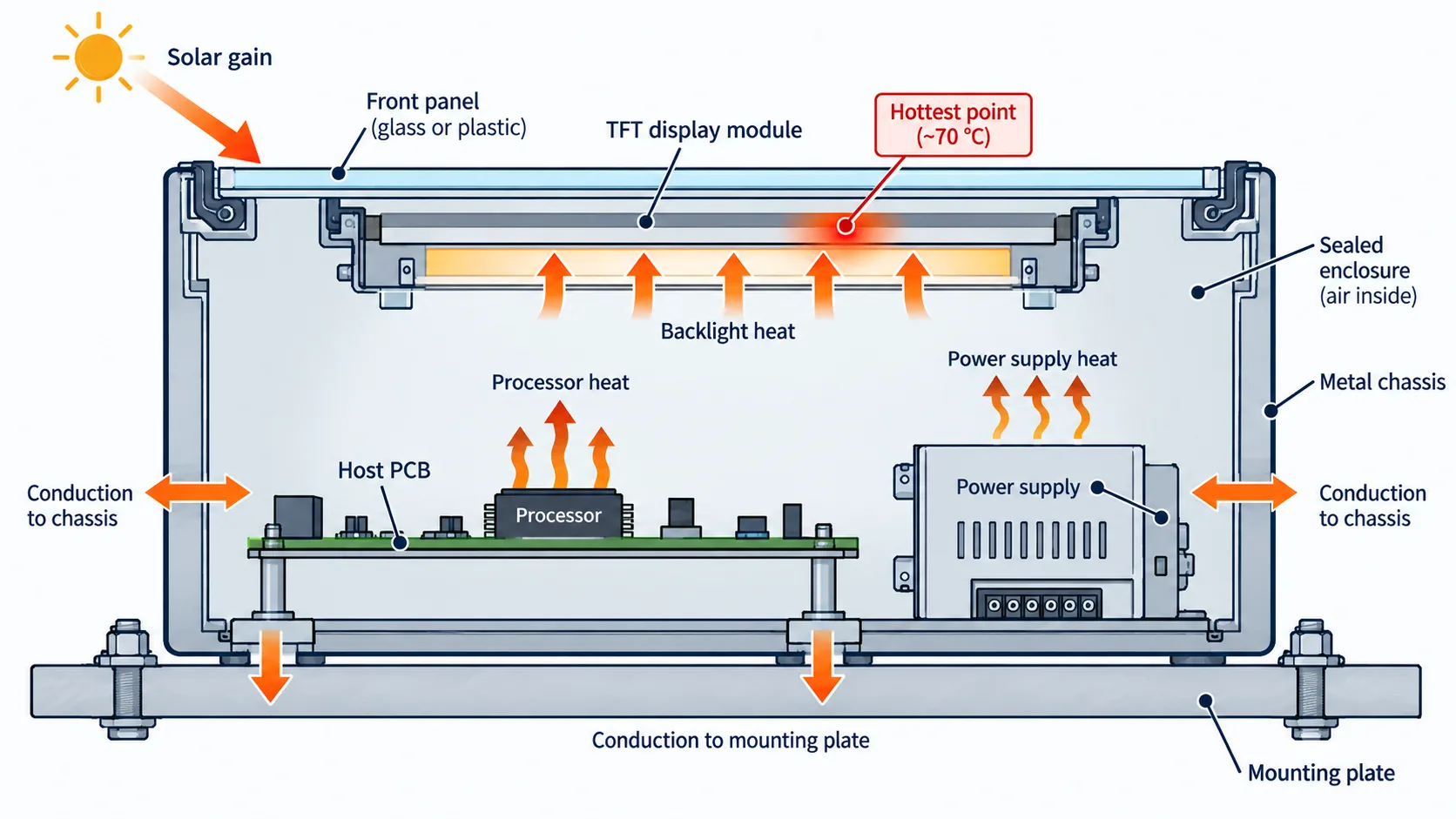
Panel datasheets define their limits at a specified measurement point on the module — commonly the LCD surface or the metal frame — not the air in your cabinet. Between cabinet air and that point sit three heat sources you own:
- The backlight. A 1000 cd/m² module dissipates substantially more than a 400 cd/m² one of the same size, and nearly all of it becomes heat inside your enclosure.
- Solar load. A display behind glass in direct sun absorbs energy that has nothing to do with the air temperature. Panel-surface temperature can be materially above ambient, so measure the assembled equipment under the intended exposure.
- Everything else in the box. The host board, the power supply and the touch controller all sit inside the same sealed volume, which for an IP-rated enclosure has no airflow at all.
This is why a "−30 to 85 °C" module and a 60 °C maximum ambient specification do not automatically add up to 25 °C of margin. The high-brightness thermal trade-off guide works through the power and heat-path side of the same problem. For sealed outdoor housings, treat the display as a heat source in the enclosure model, not as a component that merely has to tolerate the result.
Heaters: When They Help and When They Hide a Problem
A film heater behind or around the panel is a legitimate solution for equipment that genuinely must start below the coldest module available. It is also a common way to paper over a selection mistake, and it carries four costs that must be designed in from the start: peak current at the worst moment for a battery or solar supply, a temperature sensor and control loop that has to fail safe, a warm-up delay before the equipment is usable, and a new thermal gradient across the glass that can create its own uniformity artefacts. It also does nothing for a module that was stored below its storage limit. Price the wider-range module first; choose the heater second, with the numbers written down.
A Selection Sequence
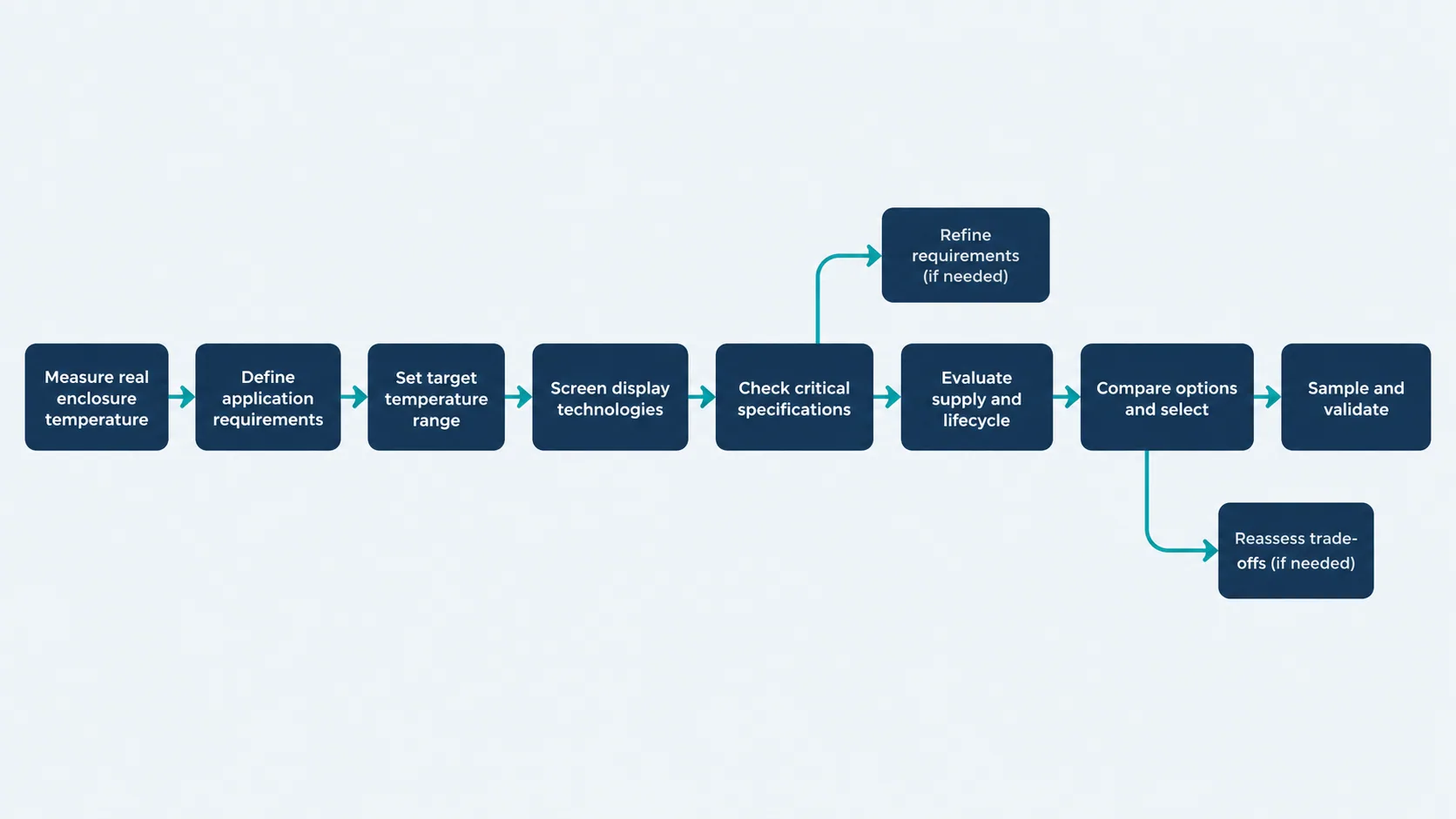
- Write the four temperatures — storage, non-operating field, operating, start-up — with the duration of each. "−40 °C for 72 hours in transit" is a requirement; "cold climate" is not.
- Check the storage minimum first on every candidate, and reject on that line before looking at anything else.
- State the start-up requirement as a time to readable image at a stated temperature, and ask whether it is specified or must be tested.
- Estimate panel-surface temperature at worst-case hot: ambient, plus backlight self-heating, plus solar load, plus everything else in the enclosure.
- Compare that number to the operating maximum, not the ambient specification to the operating maximum.
- Check the backlight driver's cold compliance voltage against the string's worst-case cold forward voltage.
- Decide whether luminance must hold over life at temperature; if so, ask for the lifetime test condition, not just the range.
- Only then compare price and lead time across the surviving candidates.
Validation Checklist Before Approval
Chamber time is cheap compared with a field recall. Run these on the exact module, in the exact enclosure, with the exact cover lens and the exact firmware.
- Cold soak and start. Soak unpowered at the cold limit for the full duration your application implies, then power on and record the time to readable image and the time to specified response.
- Hot soak at full brightness. Run at maximum backlight current at the hot limit and log panel-surface temperature, not chamber temperature. Check for luminance drop, colour shift and mura.
- Thermal cycling. Cycle across the operating range for the number of cycles the product life implies, watching for FPC and connector intermittency and for optical-stack delamination.
- Condensation and dew. Move from cold to warm humid conditions with the unit sealed as shipped, and inspect for internal condensation and for touch misbehaviour while wet.
- Backlight driver over range. Verify regulation and dimming linearity at both limits, not at 25 °C only.
- Optical measurement at temperature. Measure luminance and contrast at the extremes rather than assuming the 25 °C figure holds.
- Storage excursion. If shipping can exceed the storage limit, either test to the real excursion or document the control that prevents it.
These sit alongside the mechanical, interface and optical items in the general industrial TFT LCD requirements checklist, and they are the ones most likely to be skipped under schedule pressure.
On the figures in this article. All operating and storage ranges, luminance values and interfaces in the table are taken from our published module data and must be confirmed against the current datasheet for the exact part before design-in. Statements about liquid-crystal viscosity, LED forward voltage and LED lifetime behaviour are general physical behaviour, not specifications for a particular module. No certification, rating or test result is claimed for any product here.
FAQ: Wide-Temperature TFT LCD Selection
What does a −30 to 85 °C operating range actually guarantee?
It states the range over which the panel maker specifies the module to operate, at a defined measurement point on the module, usually with the display already running. It does not by itself guarantee start-up at the cold limit, a specified response time at the cold limit, or backlight lifetime at the hot limit. Those are separate items and must be confirmed in the datasheet or by test.
Why is the storage range sometimes no wider than the operating range?
Because different mechanisms set them. Operating limits follow the liquid crystal and the electronics; storage limits follow materials — polarisers, adhesives and sealants. Several industrial modules publish a storage range identical to the operating range, which means unheated shipping and warehousing can fall outside specification even when the installed application is comfortably inside it.
Will a wide-temperature panel start at its minimum operating temperature?
Not necessarily. Liquid-crystal viscosity rises steeply as it cools, so the first frames after a cold power-up can smear or look dim before the module self-heats. Some datasheets define a separate start-up temperature; many specify response time at 25 °C only. If a readable screen is required within a set time after cold power-on, write that as a requirement and test it.
Is high brightness a liability at high ambient temperature?
Frequently, yes. A high-brightness backlight adds self-heating on top of ambient and solar load, LED output falls as junction temperature rises, and degradation accelerates. In hot installations the limiting factor is usually the thermal path out of the backlight rather than the published upper operating limit.
Do I need a heater, or a better module?
Check the module first. A heater costs peak current when the supply is weakest, needs sensing and fail-safe control, delays availability at power-on, and does nothing about a storage excursion. It is the right answer when the requirement genuinely exceeds what any candidate module offers, and the wrong answer when it is compensating for a selection made on the operating line alone.
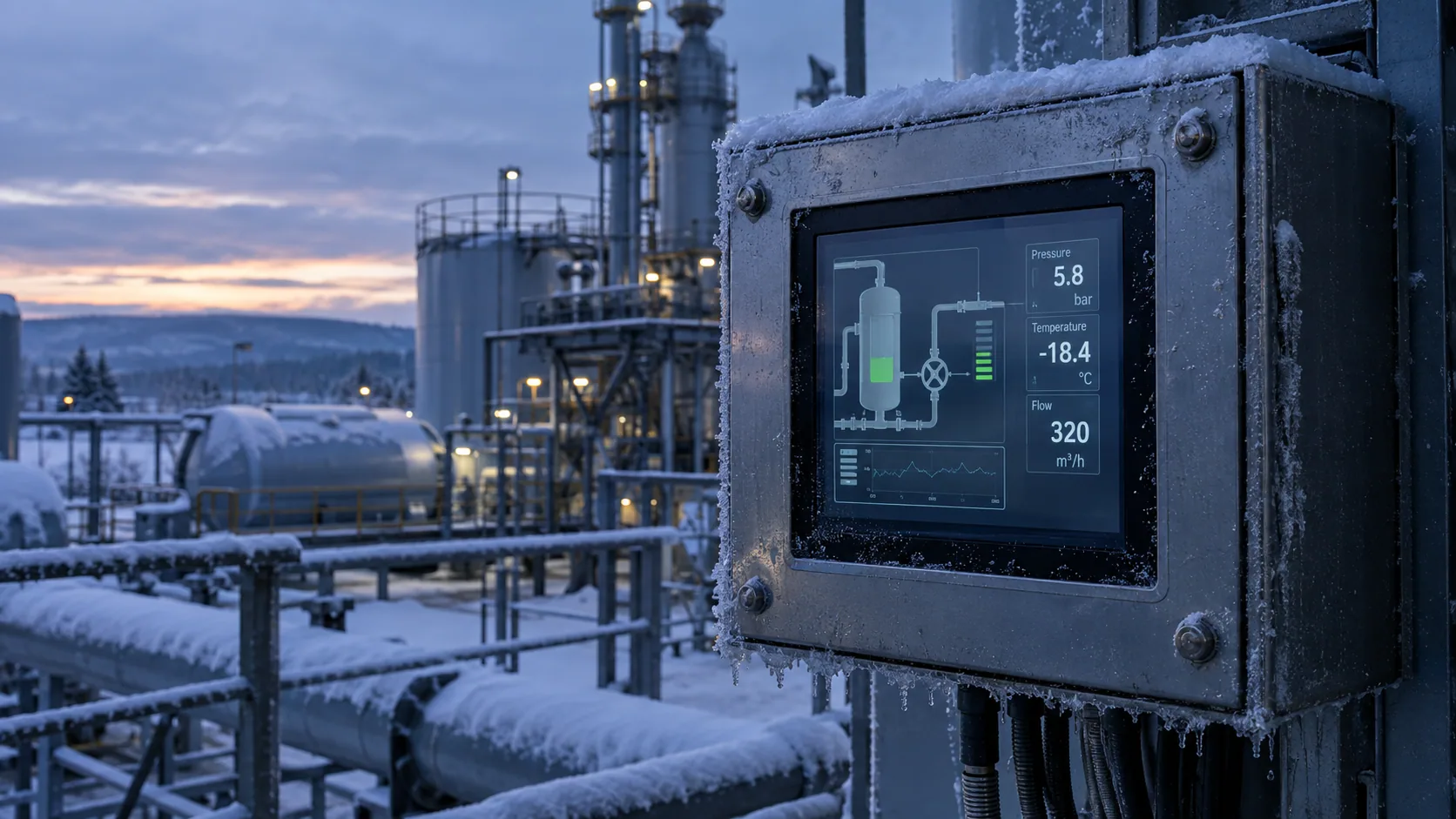
If you are specifying for an unheated outdoor cabinet, a vehicle, cold storage or an installation that sees both extremes in the same week, the outdoor equipment application notes and the wide-temperature category are the fastest places to start, and a project review is the fastest way to close the four numbers.