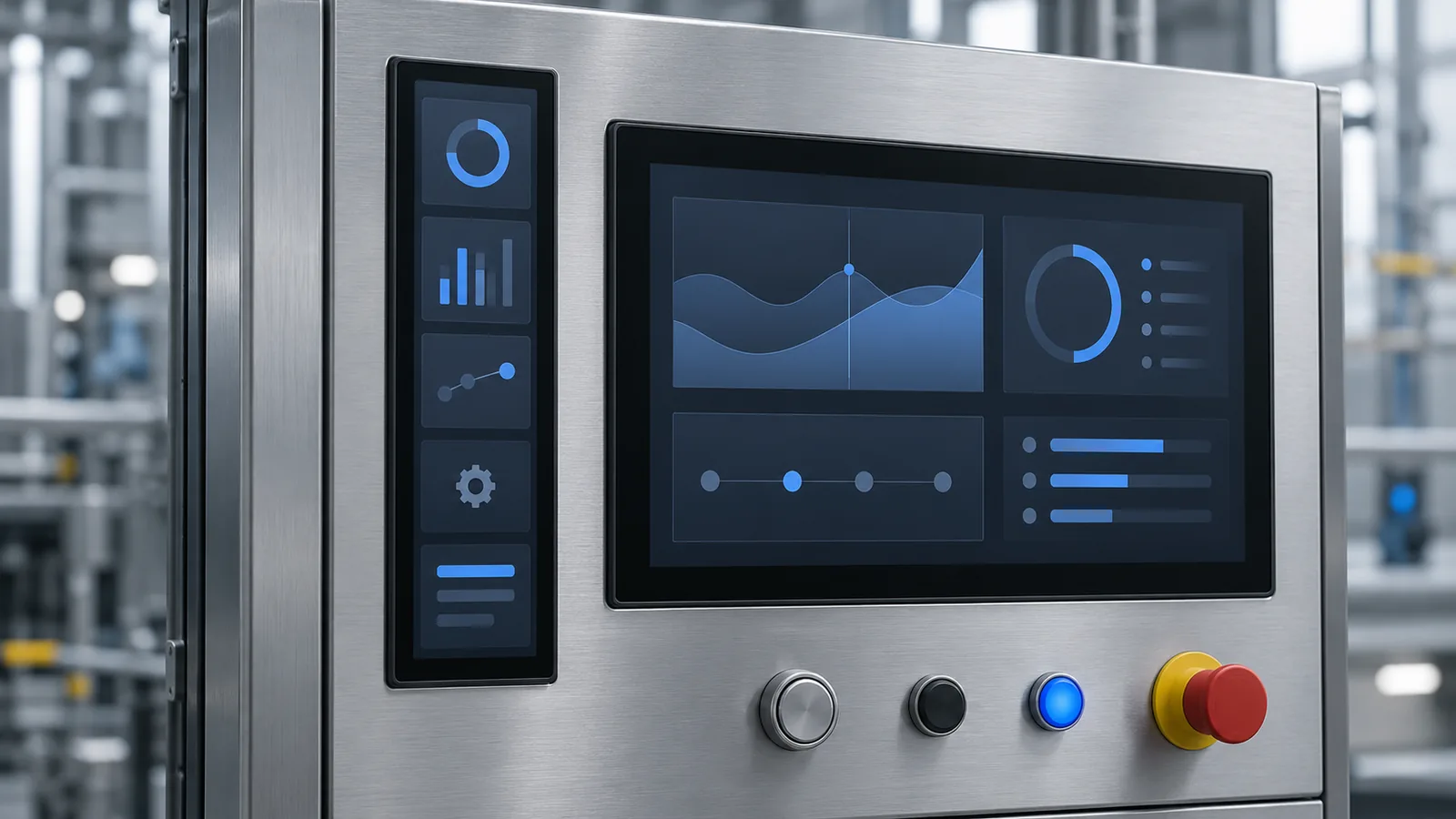
Most TFT LCD shortlists begin with a diagonal size and a common aspect ratio. Some products do not have room for either. A narrow equipment column, a control strip beside a main screen or a vertical status panel may call for a display that is roughly three to four times taller than it is wide. These stretched formats are usually called bar-type TFT LCDs.
This guide explains how to decide whether bar type is the right shape, which host and interface checks matter, how to approach UI layout and mounting, and how to validate samples. The published TFTWorks examples are the 6.8-inch DS-T068BZSA-01 and the 7.8-inch DS-T078VYRA-01; browse them with the other bar-type TFT LCD modules.
What “bar type” means
There is no single standard definition. A bar-type display is a TFT module with a much longer side than short side, defined by its active area, pixel resolution and outline rather than a common diagonal. The two published modules show the idea:
| Model | Size / resolution | Panel | Luminance | Interface | Other listed data |
|---|---|---|---|---|---|
| DS-T068BZSA-01 | 6.8 in, 480×1280 | IPS bar | 450 cd/m² | 4-lane MIPI, 40-pin | Operation −20 to +70 °C |
| DS-T078VYRA-01 | 7.8 in, 400×1280 | IPS bar | 600 cd/m² | 4-lane MIPI, 40-pin | Listed without a touch panel |
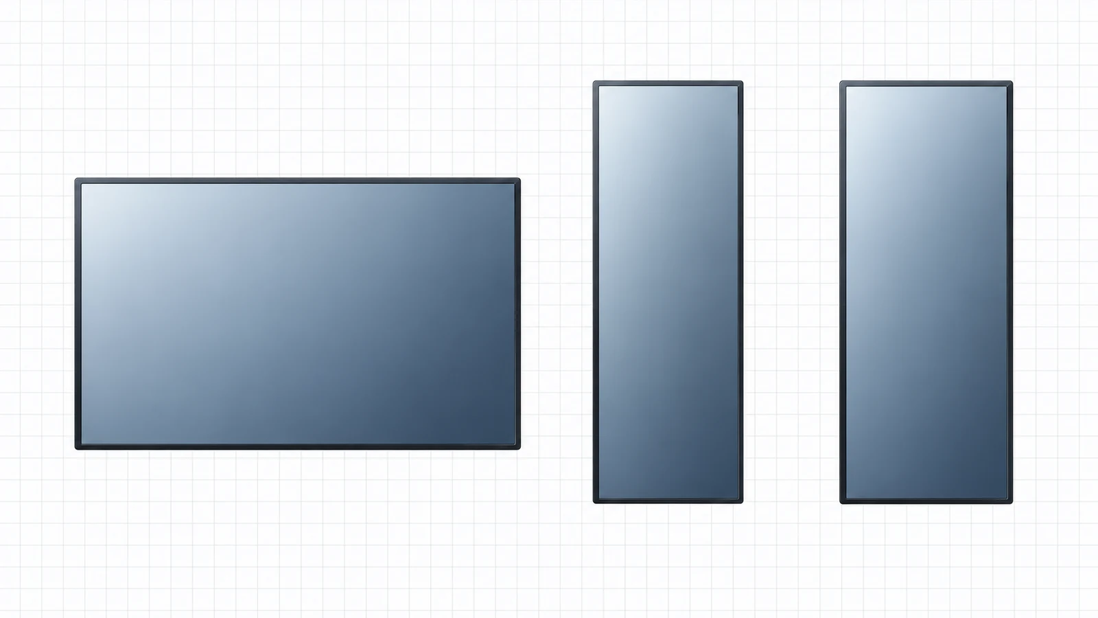
Use the published active area and approved drawing rather than estimating physical dimensions from a rounded diagonal. Pixel ratios help with UI planning, but they do not define the glass, mounting opening or FPC envelope.
| Model | Resolution / pixel ratio | Published geometry | Before designing the opening |
|---|---|---|---|
| DS-T068BZSA-01 | 480×1280 / 3:8 | Module outline: 181.20×66.85×4.70 mm (long side×short side×depth) | Confirm active area, orientation and protrusions against the approved drawing |
| DS-T078VYRA-01 | 400×1280 / 5:16 | Active area: 59.40×190.08 mm; module outline: 67.60×205.78×7.25 mm | Confirm mounting tolerance, FPC route and the full assembly envelope |
When bar type is the right shape
Bar type is a means to a layout goal, not a goal by itself. Compare it with the other ways to fill the same opening:
| Option | Strength | Trade-off to review |
|---|---|---|
| Standard 16:10 or 4:3 module behind a mask | Familiar interfaces, more module choices | Unused active area, a wider enclosure, wasted brightness and cost behind the mask |
| Two or more small displays | Flexible layout | Two interfaces, two backlights, two assemblies and more validation |
| Custom-size panel | Tailored to the opening | Different engineering effort, tooling and volume considerations; discuss early through the engineering customization review |
| Bar-type module | Uses a narrow opening efficiently with a standard-product path | Native MIPI host path, portrait-first UI, long narrow glass handling |
Typical fits include a vertical control strip beside a main display, a narrow equipment door or column, and a status or navigation panel. These are illustrative layout categories, not documented TFTWorks customer installations.
Portrait-native UI design
The published modules are specified with the long side as the vertical resolution, so the native frame is portrait. If the equipment mounts the module rotated, confirm rotation in the host, graphics pipeline or supported display configuration and the UI must still be designed for the narrow format at native pixel dimensions. Check these points early:
- Design at native size. Mock up screens at 480×1280 or 400×1280 pixels rather than scaling a landscape layout.
- Plan for narrow text columns. A short line length limits labels; use stacked cards, vertical lists, icons and short units.
- Size touch targets physically. If touch is added, convert pixels to millimeters using the active area from the drawing.
- Check viewing direction. IPS helps with consistency, but rotating a panel changes which viewing direction is critical — see the IPS vs TN guide.
- Confirm framework support. Some UI stacks assume landscape defaults; confirm rotation, custom resolution and scaling in the actual software.
Host and MIPI DSI checks
Both published bar-type modules use a 4-lane MIPI DSI interface. Compatibility is more than a matching connector: the host needs a DSI output with enough lanes and rate, support for the panel's resolution and timing, and the initialization sequence. Review the general TFT LCD interface guide and calculate the link with the MIPI DSI lane selection guide.
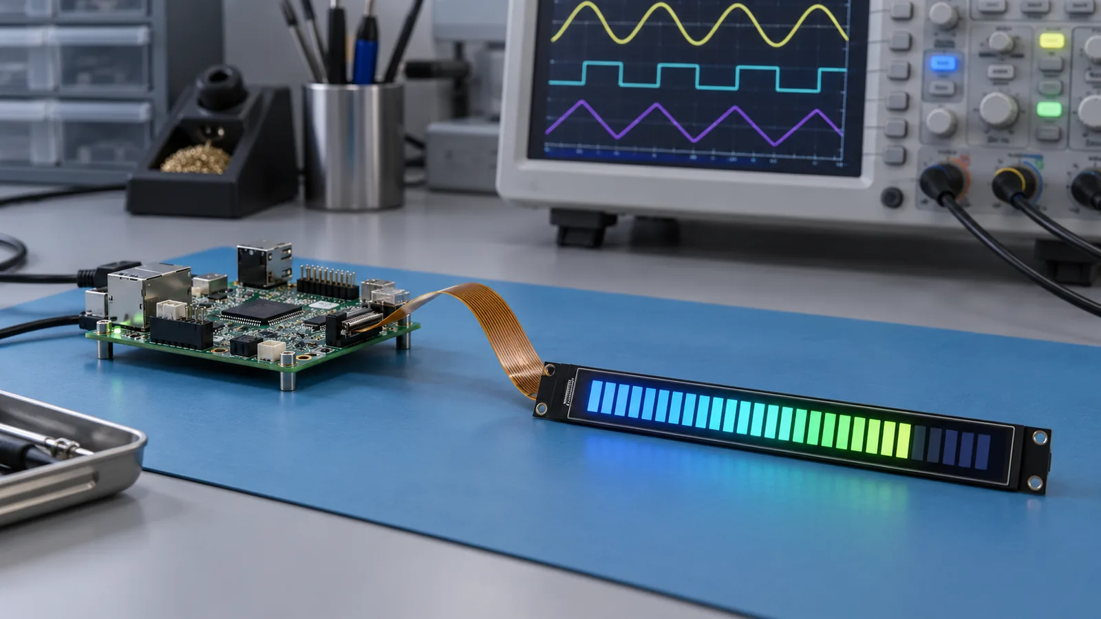
An illustrative payload calculation helps size the host. The numbers below use active pixels at an assumed 60 Hz and 24 bits per pixel. They are not module specifications; real lane rates are higher because of blanking, packet and protocol overhead and depend on the panel's timing table.
| Resolution | Active pixels | Frame buffer, 24 bpp | Frame buffer, 32 bpp | Active payload at 60 Hz, 24 bpp | Per lane across 4 lanes |
|---|---|---|---|---|---|
| 480×1280 | 614,400 | ≈ 1.84 MB | ≈ 2.46 MB | ≈ 885 Mbit/s | ≈ 221 Mbit/s |
| 400×1280 | 512,000 | ≈ 1.54 MB | ≈ 2.05 MB | ≈ 737 Mbit/s | ≈ 184 Mbit/s |
Then work through the host-side questions:
- Does the host expose 4 DSI lanes at the required rate, and can the display pipeline output this resolution?
- Can it be configured with the panel's timing and initialization commands, including reset and sleep/wake?
- Is a driver or device-tree entry available, or does it need to be written and maintained?
- Is a bridge needed? If the host offers only RGB, LVDS or HDMI, a conversion path adds board area, power, software and EMC work. Evaluate it with the controller board selection guide before choosing the module.
- Is the bring-up recorded? Save the initialization revision and host settings, and use the interface troubleshooting workflow if the image is missing or unstable.
Mechanical, FPC and front-stack planning
A long, narrow glass behaves differently from a compact module. Review these items on the approved drawing and in a physical sample:
- FPC tail and connector position. Check bend radius, routing past the enclosure and strain relief. A mismatch can be handled through FPC and pinout customization.
- Mounting and flatness. A long module can flex or twist if it is clamped unevenly; check the mounting scheme, gasket compression and adhesive.
- Cover lens and bonding. A cover glass or touch sensor over a narrow stack adds tolerance and warp considerations. See the cover glass design guide and optical bonding guide.
- Heat distribution. The backlight and driver heat is concentrated in a small footprint; check the temperature of the finished enclosure, not only the module.
Brightness, viewing and environment
The two published modules list 450 and 600 cd/m², so confirm that the target reads well in the real light. For bright-ambient or outdoor-facing use, read the brightness-class comparison and the sunlight-readable TFT LCD guide. The 6.8-inch module's listed operating range of −20 to +70 °C should be compared with the installed enclosure temperature, using the wide-temperature selection guide. For a sunlit or washed-down panel, review the complete front stack rather than the bare module.
Sample validation checklist
- Confirm the approved drawing, pinout, timing and initialization revision for the exact model.
- Verify the host's 4-lane MIPI DSI output, lane order and polarity on the intended FPC route.
- Test the real UI at native resolution in the final rotation, including thin lines and small text.
- Check the image from the user positions, at the intended mounting tilt.
- Measure brightness and backlight temperature inside the finished enclosure.
- Check mounting stress, flatness and the FPC bend after assembly and after a thermal cycle.
- Record results with photos, settings and sample revision so they are reproducible in production.
The sample validation checklist and requirements checklist provide the broader framework.
Bar-type TFT LCD FAQ
Can a bar-type TFT LCD run from a standard HDMI or LVDS output?
Not directly. The published bar-type modules use a native 4-lane MIPI DSI interface, so the host needs a compatible DSI output and the panel's initialization and timing. If the host offers a different output, a bridge or controller board becomes part of the display architecture and must be evaluated for cost, size, power, software and EMC.
Can a bar-type display be cut from a larger panel?
Do not cut or trim a supplied finished TFT module. Some manufacturers resize panels using controlled factory processes, but that is not a user modification or a capability claimed for these modules. Order an approved bar-format module with its own drawing, driver and backlight configuration.
Is the UI designed in portrait or landscape for a bar-type display?
The published modules are specified with the long side as the vertical resolution, so the native frame is portrait. Equipment can mount them rotated, but the host must then rotate the frame and the UI must be designed for the narrow format at its native pixel dimensions.
Can a bar-type TFT LCD have a touch screen?
Check the touch status on each model's product page. A touch front stack on a long narrow format needs project review of the cover glass, sensor, bonding and flatness, so request a review rather than assuming a standard option exists.
Technical references
- MIPI Alliance — Display Serial Interface (MIPI DSI): official overview of the high-speed serial display interface.
Send Us Your Opening and Host Details
Share the opening or enclosure drawing, host processor and display output, target UI orientation and operating environment. TFTWorks can review the published bar-type modules or an FPC and interface adaptation path against the exact configuration.
Publisher and scope. Published by TFTWorks, operated by Guangdong Dexing Microelectronics Co., Ltd. Published geometry and calculated payload figures are for planning only and do not replace the controlled datasheet, drawing or sample acceptance. Request the current model-specific datasheet and drawing before release.