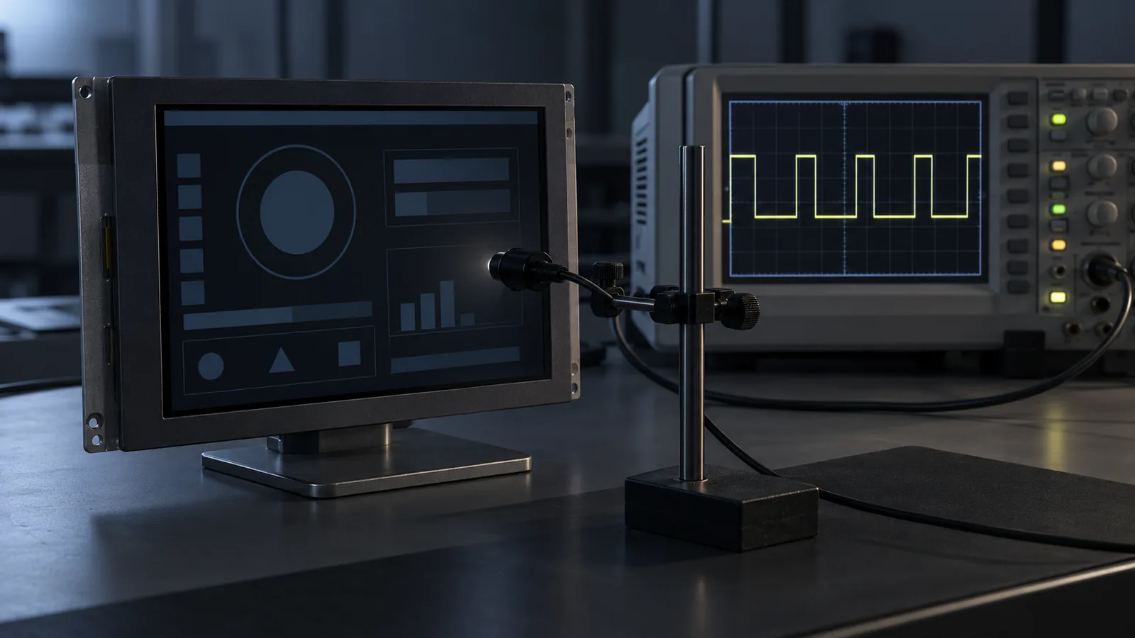
Backlight dimming looks like a firmware setting until a customer reports a buzzing screen, a flickering display at night, or dark bars in a camera view. These problems appear in the field because the dimming method was never tested across the whole range. This guide explains how TFT LCD backlights are dimmed, what each method trades off and how to validate the result.
It focuses on dimming behavior. For how dimming affects lifetime, read the backlight lifetime guide, and for heat, the thermal trade-offs guide.
Where dimming happens
A TFT LCD does not dim itself. The LED backlight is dimmed by a driver, and the driver can live in three places: on the display module, on a controller board, or on your host board. That decides who owns the dimming method, which input you must provide and what you can change. Confirm it in the controlled datasheet and the approved drawing. If a published summary does not list the backlight type, current or power, as on some product pages, request the current datasheet before you design the host board. Read how to read a TFT LCD datasheet for what to look for.
PWM vs analog vs hybrid
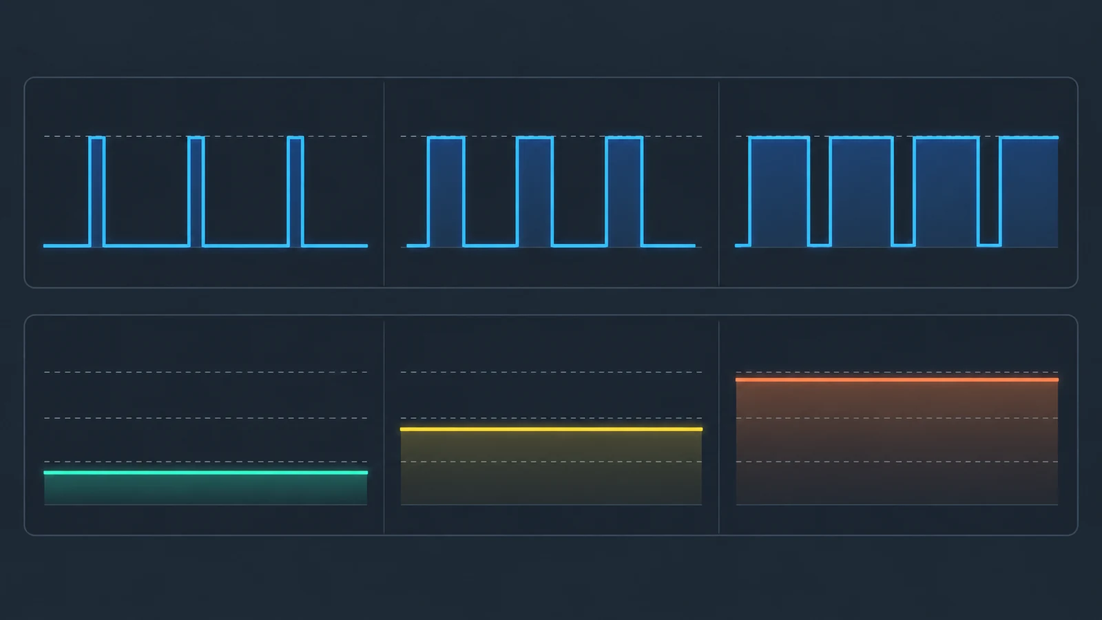
The three methods differ in how they change the LED current:
- PWM (pulse-width modulation). The LED current is switched on and off at a fixed frequency, and brightness follows the duty cycle. Each pulse carries the full LED current.
- Analog (current) dimming. The LED current is held steady and set to a lower value. Brightness follows the current.
- Hybrid. Analog dimming covers the upper range, and PWM takes over at very low brightness.
| Aspect | PWM | Analog | Hybrid |
|---|---|---|---|
| EMI | Pulsed full current can radiate and conduct noise | Steady current; usually less EMI | Less EMI than PWM alone, since PWM works at lower current |
| Efficiency | Depends on the driver | Can be better than PWM | Between the two |
| Flicker | Possible; depends on frequency and modulation depth | No deliberate on/off PWM modulation; check actual driver ripple | Only at the low end, where PWM is active |
| Audible noise | Possible if the frequency is audible and the driver uses ceramic capacitors | No PWM excitation from this dimming method; other driver noise still needs checking | Only at the low end |
| Color at low level | Stable, since the LEDs run at the same current when on | A slight hue shift is possible at very low levels | Hue shift limited by switching to PWM |
| Low-end range and matching | Wide range is easy to reach | Current matching between LED strings can degrade at very low current | Lets the current stay above the matching limit |
| Complexity | Low | Needs a driver that supports it | Highest; needs a defined crossover |
Two of these points come from a Texas Instruments application report on analog dimming with a specific LED driver. It states that analog dimming causes less EMI and achieves better efficiency than PWM dimming, notes a slight hue shift at very low dimming levels, and recommends combining analog and PWM dimming for very low brightness, pulsing between 0 and a low current instead of between 0 and the full current to reduce EMI and improve current matching. Those results belong to one driver family, so treat them as direction, not as numbers for your design.
Flicker and PWM frequency
With PWM dimming, the light output switches on and off. Whether the user sees it depends on the frequency, the modulation depth (how far the light drops between pulses) and how the user looks at the screen. At low brightness the duty cycle is small, so the modulation is deep, and fast eye or head movement can reveal the pulses to some people.
The MAX20444 application article discusses a 100 Hz lower bound in that driver context while balancing flicker against audible noise. This is not a universal display acceptance threshold or a recommended target: confirm the exact driver limits and validate the actual light output across the dimming range. For a broader reference, IEEE 1789-2015 is a recommended practice for lighting that relates flicker risk to modulation depth and frequency, and its guidance suggests testing across the full dimming range, since flicker can change with dimming level. It is a lighting document, not a display standard, so use it as a way to think about the problem and then test your actual product.
Audible noise
PWM dimming can make a screen hiss or buzz. One possible cause is the ceramic output capacitors in the LED driver: when the LED current is pulsed, the multilayer ceramic capacitors can resonate mechanically through the piezoelectric effect of the dielectric, and the vibration couples into the circuit board. The effect is most likely when the PWM frequency lies in the audible range of about 20 Hz to 20 kHz.
Mitigations from the same application article include moving the PWM frequency outside the audible band, using capacitor types that do not resonate (such as polymer or electrolytic parts), choosing low-noise ceramics, and changing layout and mounting so the vibration does not couple into the board. This matters most for quiet environments such as bedside medical equipment and instruments; see the medical equipment display guide. Check it in a quiet room, at the dimming levels users actually use.
Camera banding and beating
If a camera sees the screen, PWM dimming can show up as dark bands or flicker in the image. This happens because the camera's exposure and readout can sample the pulsed light unevenly. It matters for equipment that is filmed, for vision-based test setups and for vehicles or devices with cameras that capture the display. A PWM frequency close to the display refresh rate, or to a harmonic of it, can also produce a slow visible beating.
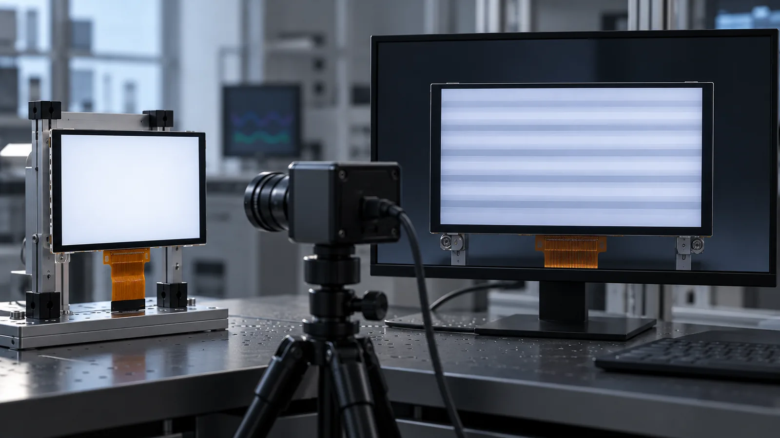
Test with the camera, lens settings and exposure your product uses, at several brightness levels. Do not assume that a screen that looks steady to the eye will look steady to a camera.
Minimum brightness and the dimming curve
Many industrial products are used in dark places such as cabins, control rooms, bedsides and night-time vehicles. Define the lowest brightness the product must reach and check it on a sample. Three points help:
- Perception is not linear. Equal steps in duty cycle or current do not look like equal steps in brightness, especially at the low end. Use a lookup table or curve so the slider feels even.
- The low end is where problems concentrate. Flicker, banding, noise and color shift are all most likely at the lowest levels. Test the minimum, not just the middle.
- Power-up behavior counts. Define the backlight state during boot so the screen does not flash at full brightness before your software sets the level. Follow the module's power-sequencing notes.
EMI and the control signal
A pulsed LED current is a source of noise, and PWM edges can radiate or conduct into other circuits. Analog dimming generally causes less EMI, and a hybrid method lowers the pulse current at the low end. Include the backlight driver in EMC pre-compliance checks with the real enclosure, cable and power supply; the EMC and electrical planning notes in the medical guide show the checks. Keep the PWM input to the driver clean as well: routing it next to a display link or touch lines can couple noise in both directions.
Host control options
The input your host must provide depends on the driver:
- A PWM input. The host or a microcontroller generates a PWM signal at a stated frequency range. Check the allowed frequency, the minimum duty cycle and the logic level.
- An analog voltage input. A DAC or filtered output sets the current. If a PWM signal is low-pass filtered into an analog voltage, the filter must remove enough ripple at the PWM frequency; the Texas Instruments report uses at least 20 dB of attenuation in its example.
- A digital interface. Some drivers accept brightness commands over a serial bus, which can add dimming curves and protection features.
If the host cannot supply the input the driver needs, a controller board may take over the dimming function, which changes the design and the validation.
A dimming validation plan
| Test | How | What to look for |
|---|---|---|
| Light output waveform | Photodiode on the screen with an oscilloscope, at minimum, mid and maximum brightness | Frequency, duty cycle and modulation depth of the actual light, not only the control signal |
| Full-range sweep | Step through the whole dimming range, including very low levels | Visible flicker, steps, flashing or color shift |
| Audible noise | Listen in a quiet room at normal listening distance, across the range | Hiss or buzz, especially at low brightness |
| Camera test | Film the screen with the product's camera and exposure settings | Dark bands or beating |
| Boot and transitions | Power-cycle, wake from sleep and change brightness quickly | Flash at full brightness, glitches or flicker during changes |
| EMC pre-scan | Run with the real enclosure, cable and supply | Emissions at the PWM frequency and its harmonics |
| Thermal and lifetime | Run the real brightness profile and log temperature | Backlight and driver heat; see the lifetime guide for duty-cycle planning |
The sample validation checklist shows how to freeze the configuration and record the results so they can be repeated in production.
Questions to ask the supplier
- Where is the backlight driver: on the module, on a controller board or on my board?
- What dimming methods does it support, and what input does it need?
- What PWM frequency range and minimum duty cycle are allowed?
- What is the usable dimming range, and how does the light output behave at the low end?
- What are the LED string current, voltage and power at the working brightness?
- Does the lifetime figure assume a dimming method, frequency and duty cycle, and what is the end-of-life criterion?
- What is the power-up and power-down sequence for the backlight?
- Can the dimming method or frequency be changed for my application?
Backlight dimming FAQ
Should an industrial TFT LCD use PWM or analog backlight dimming?
Neither is best everywhere. PWM is simple and reaches low brightness easily, but it can bring flicker, audible noise, EMI and camera banding. Analog (current) dimming usually causes less EMI and can be more efficient, but color can shift slightly at very low levels. Many designs use analog dimming for the upper range and PWM for very low brightness. Test the real driver, module and use case.
What PWM frequency should I use for a backlight?
There is no universal value. Start from the driver's allowed range, keep the frequency high enough to avoid visible flicker, and consider keeping it out of the audible band to avoid noise from the driver's ceramic capacitors. Then test with your real screens, your cameras and your lowest brightness, because flicker and banding can change across the dimming range.
Does dimming the backlight extend its life?
Not in a simple linear way. Lifetime depends on LED current, temperature and the dimming waveform, including PWM frequency, duty cycle and peak current. Ask the supplier for the lifetime definition and conditions, and validate the real operating profile.
Why does my display buzz or hiss when I dim it?
When a PWM signal pulses the LED current, ceramic output capacitors in the driver can vibrate through the piezoelectric effect and the sound can couple into the board. It is most likely when the PWM frequency lies in the audible range. Raising the frequency out of the audible band, or changing the capacitors and layout, can reduce it.
Technical references
- Texas Instruments — Analog Dimming with the TPS61181 (SLVA493): compares PWM and analog dimming for a specific LED driver, including EMI, efficiency and low-level behavior.
- Analog Devices — How to Reduce PWM-Related Acoustic Noise on MAX20444 Applications: explains ceramic-capacitor noise under PWM dimming and mitigation options.
- U.S. Department of Energy — Flicker: understanding the new IEEE recommended practice: background on IEEE 1789 and flicker evaluation for LED lighting.
Send Us Your Dimming Requirements
Share the host's brightness control output, the lowest brightness you need, whether a camera sees the screen and any quiet-room or EMC constraints. TFTWorks can review published modules or a controller-board path against the exact configuration.
Request a Project Review Browse high-brightness modules
How to send drawings or UI screenshots
The project-review form accepts text details, not file uploads. Send your initial requirements there, or attach your files directly by email or WhatsApp. Include the reference model, your company and the project context so the files can be matched to your enquiry. Do not send confidential files without agreeing the sharing terms.
Continue the engineering review
Publisher and scope. Published by TFTWorks, operated by Guangdong Dexing Microelectronics Co., Ltd. Dimming behavior depends on the driver, the LEDs and the module, and the referenced application notes describe specific driver families. Confirm the dimming method, frequency range and lifetime conditions against the current model-specific datasheet and validate samples in your own product.