Industrial display projects often treat “50,000 hours” or another quoted lifetime as a simple procurement checkbox. The number appears precise, but it may represent different endpoints under different laboratory conditions. One supplier may mean time until the backlight reaches half of its initial luminance at a defined current and temperature. Another may present an LED-package lumen-maintenance projection. Neither automatically predicts the service life of a sealed HMI operating near a processor, under solar load and at maximum brightness.
The engineering objective is not to find the largest number. It is to connect a clearly defined backlight-life metric to the equipment’s actual duty cycle, thermal environment, optical requirement and service strategy.
The short answer
Before accepting any industrial TFT LCD backlight-lifetime claim, ask five questions:
- What is the endpoint? Is it L70, L50, catastrophic failure, color shift, uniformity loss or another definition?
- What was tested? An LED package, an LED board, the backlight unit or the complete TFT module?
- Under what conditions? Confirm current, PWM behavior, temperature measurement point, orientation, airflow and test pattern.
- Is the value measured or projected? Request test duration, projection method, sample size and stated limits.
- Does it match the application? Compare the supplier conditions with the real enclosure, ambient range, daily operating hours and brightness profile.
What does backlight lifetime mean?
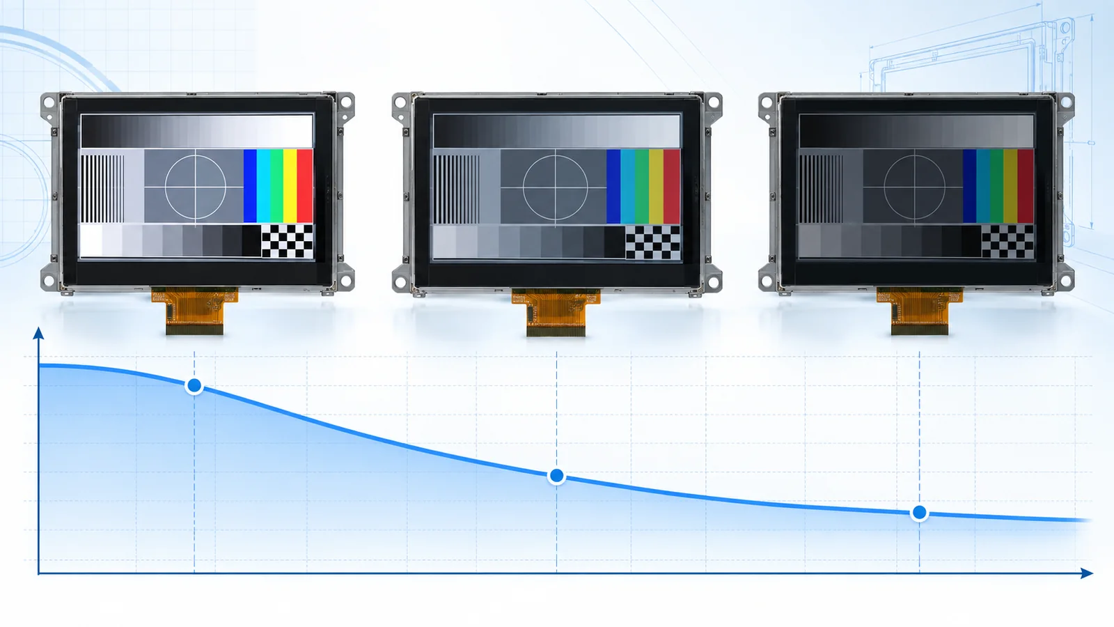
LED backlights usually lose output gradually rather than switching from full output to zero at a predictable time. A useful specification therefore needs a luminous-maintenance threshold:
- L70 generally refers to the time when output has declined to 70% of its initial value under the stated conditions.
- L50 generally refers to the time when output has declined to 50% of its initial value under the stated conditions.
- B-values, when supplied, describe a population or failure percentile associated with a maintenance target. The supplier must define the notation and statistical method.
The initial reference also matters. Ask when the baseline is measured, whether any stabilization or burn-in period is used, and whether luminance is measured at the LED source, backlight surface or finished display. If the product specification simply says “LED life” without defining the endpoint and measurement location, treat the value as incomplete.
Luminance maintenance is only one possible end-of-life mechanism. An industrial display can become unsuitable because of color shift, uneven luminance, driver failure, optical-film degradation, a connector problem or a temperature-related system fault even while most LEDs still emit light.
Verify the scope of the claim
| Claim scope | What it can tell you | What it does not prove by itself |
|---|---|---|
| LED package or array | Light-output and color maintenance for the tested source under controlled drive and temperature conditions. | Backlight uniformity, driver life, thermal interface, optical-stack aging or complete TFT-module life. |
| LED backlight unit | Behavior of the selected LEDs, PCB, light guide and optical films as assembled in the backlight. | Performance after integration with a different driver, enclosure, cover stack or thermal environment. |
| Complete TFT module | Maintenance for the defined display assembly and its specified test setup. | Service life in an OEM enclosure unless the application conditions are represented. |
| Complete equipment | Most relevant level when the production enclosure, power system, software and duty cycle are included. | Other installations or operating profiles that fall outside the validated configuration. |
IES LM-80 and TM-21 are widely referenced for LED source maintenance and projection. The Illuminating Engineering Society also emphasizes that component-level methods do not account for every mechanism in a complete lighting system. The same boundary matters in a TFT design: the backlight driver, optical stack, mechanical frame and enclosure influence system performance.
Conditions that must accompany the hour value
Request the conditions below in writing and carry them into the display specification, drawing set or approved technical agreement.
| Item to verify | Why it changes the interpretation |
|---|---|
| Endpoint and measurement location | Distinguishes L70 from L50 and source-level output from finished-display luminance. |
| LED current and string configuration | Electrical stress, current balance and driver topology affect output, temperature and aging. |
| PWM frequency, duty cycle and peak current | Average luminance alone does not describe the electrical waveform or pulse stress. |
| Temperature and measurement point | Ambient, LED-board, solder-point and junction temperatures are not interchangeable. |
| Orientation, airflow and mounting | These conditions change the thermal path and the temperature reached at a given power. |
| Test duration and projection method | Separates recorded maintenance from a longer-term projection and exposes extrapolation limits. |
| Sample quantity and failure handling | A typical curve for one sample is not a population or reliability statement. |
| Allowed color and uniformity change | Average luminance can remain acceptable while visible image quality becomes unacceptable. |
Junction temperature is highly relevant to LED performance, but it is difficult to measure directly in a finished module. A supplier may use a defined temperature-measurement point and thermal-resistance model. Ask exactly where the sensor is placed and how junction temperature is estimated; do not substitute enclosure-air temperature for an undefined LED temperature.
Convert operating hours into an application duty cycle
Calendar life begins with a simple relationship:
Illustration only: 50,000 operating hours corresponds to about 5.7 years at continuous 24/7 operation, about 11.4 years at 12 hours every day, or about 24 years at 8 hours per day and five days per week. These arithmetic conversions are not a warranty and remain valid only if the referenced lifetime conditions match the application.
Real duty cycles are often more complex. Include standby dimming, peak-brightness intervals, seasonal operation, warm-up time, maintenance shutdowns and display-off modes. Record whether the hour counter runs whenever the equipment is powered or only while the backlight is enabled.
Dimming does not automatically make lifetime scale linearly with duty percentage. PWM can reduce average light and power while retaining the programmed peak current during each pulse. Analog dimming changes current in another way. The driver, LED data and validated operating profile must be evaluated together.
Backlight problems are not always LED wear
A complete root-cause review should distinguish gradual maintenance loss from other failures:
- Unequal current among strings causing bands, dark zones or accelerated mismatch.
- Open or shorted LED strings and the driver’s response to those faults.
- Boost-converter, inductor, diode, MOSFET, connector or capacitor degradation.
- Light-guide, reflector or diffuser change that reduces output or uniformity.
- Polarizer, adhesive, cover or optical-bond material change in heat, UV or humidity.
- Intermittent FPC or harness connections after vibration or thermal cycling.
- Thermal protection or software control reducing brightness as designed.
This is why a component projection cannot replace validation of the complete product. If the screen becomes dim, measure backlight current, voltage, temperatures, output and uniformity before assuming normal LED depreciation.
Review the backlight driver with the display
The controller or carrier board must support the backlight’s electrical requirements across input-voltage and temperature limits. Verify string voltage, current per string, current matching, startup behavior, dimming range, minimum pulse behavior and protection for open or short LED conditions. Include driver efficiency and nearby heat sources in the thermal budget.
If a separate controller board is planned, use the TFT LCD controller-board selection guide to check video compatibility, power sequencing and backlight control together. An electrically compatible image interface does not guarantee that the board is a suitable long-life backlight driver.
A practical backlight-lifetime validation plan
- Define useful end of life. Set minimum luminance at the viewer, acceptable uniformity and color change, plus any catastrophic-failure criteria.
- Record an optical baseline. Measure production-intent samples after the defined stabilization period using a controlled pattern, geometry and temperature.
- Instrument the thermal path. Measure the LED-board location specified by the supplier, the driver IC and power components, nearby enclosure surfaces and ambient air.
- Use worst-case production conditions. Test maximum brightness, the real enclosure, maximum equipment load, expected orientation and relevant ambient or solar conditions.
- Exercise the operating profile. Include startup, dimming transitions, continuous high output, standby and thermal-control behavior.
- Track drift, not only pass/fail. Record luminance, uniformity, color, current, voltage and temperature at defined intervals.
- Control changes. Treat changes to LEDs, optical films, PCB, driver components, adhesives or suppliers as review triggers.
Select the display around the real requirement
Start with the luminance and ambient-contrast target rather than driving every project at the maximum available backlight level. The 800 vs 1000 vs 1200 nit selection guide explains why the highest nominal luminance is not always the best system choice. Reflection control and a properly reviewed optical-bonding stack may improve ambient readability without relying only on more backlight power.
TFTWorks lists high-brightness TFT modules and wide-temperature display options as engineering starting points. Published catalog values do not replace confirmation of current backlight-life conditions for the exact model and production revision. Request the applicable datasheet, drawing and approved specification during project review.
Supplier questions before design freeze
- What exact L-value or failure criterion defines the quoted lifetime?
- Is the value typical, minimum, calculated, projected or verified by test?
- What component or assembly does it cover?
- What are the LED current, PWM, temperature and mounting conditions?
- What is the temperature measurement point and how is junction temperature estimated?
- What sample quantity, data duration and projection method support the claim?
- Are color, uniformity and failed-string limits included?
- Which driver and protection assumptions were used?
- What changes require customer notification or requalification?
- What application-level tests are recommended for the target enclosure?
Add these questions to the broader industrial TFT LCD requirements checklist so backlight lifetime is reviewed alongside interface, touch, mechanics, environment and supply continuity.
Related engineering guides
Technical references
- Illuminating Engineering Society — ANSI/IES LM-80-21: controlled measurement of light-output and color maintenance for LED packages, arrays and modules.
- Illuminating Engineering Society — ANSI/IES TM-21-21: projection of long-term maintenance from LM-80 data and its stated limits.
- Illuminating Engineering Society — PS-10-18: why LED-source maintenance methods do not by themselves describe every complete-system failure mechanism.
- ams OSRAM — Reliability and Lifetime of LEDs: relationships among current, temperature, thermal design, maintenance and LED reliability.
- Newhaven Display — example TFT module datasheet: an example of explicitly defining a backlight-life endpoint and operating conditions; its values apply only to that product.