Short Answer
480×272 gives you about 128 PPI, a 255 KB frame buffer and a 9 MHz pixel clock, in a near-16:9 window measuring roughly 95×54 mm. 800×480 gives you about 217 PPI, a 750 KB frame buffer and a 33 MHz pixel clock, in a 5:3 window measuring roughly 94×56 mm. Both normally use the same 24-bit RGB parallel interface, so unlike the 3.5-inch decision this is not a change of host class — it is a change of memory budget, signal integrity effort and screen layout. Pick 480×272 when the UI is gauges, large numerals and Latin menus. Pick 800×480 when you need dense text, fine graphics, or a resolution you can carry across 4.3, 5.0 and 7.0-inch product tiers on one firmware build.
Start With the Geometry, Not the Pixel Count
The trap in this comparison is assuming that two 4.3-inch panels present the same window. They do not, because the aspect ratios differ:
- 480×272 has an aspect ratio of 1.765:1 — very close to 16:9, though not exactly. Typical active area is about 95.0 × 53.9 mm.
- 800×480 has an aspect ratio of 1.667:1, which is exactly 5:3. Typical active area is about 93.6 × 56.2 mm.
Same diagonal, different rectangle. The 800×480 window is roughly 1.4 mm narrower and 2.3 mm taller. That is comfortably enough to invalidate a bezel cutout, a gasket, a decorative overlay or a moulded lens that was drawn around the other one. If there is any chance of switching resolution later in the programme, draw the cutout to suit both from the start, or accept that a resolution change becomes a tooling change.
| Panel | Aspect | Total pixels | Approx. active area | Approx. PPI | Approx. pixel pitch |
|---|---|---|---|---|---|
| 4.3″ 480×272 (WQVGA) | 1.765:1 | 130,560 | 95.0 × 53.9 mm | 128 | 0.198 mm |
| 4.3″ 800×480 (WVGA) | 5:3 | 384,000 | 93.6 × 56.2 mm | 217 | 0.117 mm |
| 5.0″ 800×480 (WVGA) | 5:3 | 384,000 | 108.0 × 64.8 mm | 187 | 0.135 mm |
The Aspect Ratio Consequence Everybody Discovers Late
A layout designed for 1.765:1 does not scale into 5:3. It is not a matter of stretching a mock-up, because the proportions of the content change relative to each other. In practice you meet this in three places.
Header and Footer Bands Cost You Differently
A fixed 32-pixel status bar consumes 11.8% of a 272-pixel-tall screen and 6.7% of a 480-pixel-tall one. On the shorter panel, chrome eats the content area fast, which is why 480×272 interfaces tend towards a single full-bleed view with no persistent navigation.
List Views Are Where 272 Pixels Runs Out
Touch targets need roughly 9 to 10 mm of height to be reliable with a bare fingertip, and more with gloves. At 0.198 mm pitch that is about 48 pixels per row, so a 272-pixel screen holds five rows and nothing else. At 0.117 mm pitch the same 9.5 mm row is 81 pixels, and a 480-pixel screen holds five rows plus a header, a footer and breathing room. If your UI is fundamentally a list, this comparison is already settled.
Landscape Video and Camera Content Prefers the Wider One
If the panel's job is to show a 16:9 camera feed, 480×272 fits it almost exactly, while 5:3 leaves letterbox bands top and bottom. This is the one place where the lower-resolution panel has the better shape.
What the Extra Pixels Cost
Frame Buffer Memory
At 16 bits per pixel in RGB565:
- 480×272 × 2 bytes = 261,120 bytes, about 255 KB. Double-buffered, about 510 KB.
- 800×480 × 2 bytes = 768,000 bytes, about 750 KB. Double-buffered, about 1.5 MB.
That gap decides the memory architecture. A high-end microcontroller with a megabyte of internal SRAM can hold a double-buffered 480×272 image on-chip and never touch external memory. A double-buffered 800×480 image at 1.5 MB will not fit in the internal SRAM of most microcontrollers, so external SDRAM comes onto the board — with the extra pins, the extra layer count, the extra BOM lines and the extra lead-time exposure that brings.
Going to 24-bit colour makes it worse: 800×480 at 32 bits per pixel is 1.5 MB for one buffer and 3 MB for two. Most embedded UIs have no business leaving RGB565 unless they are showing photographs or smooth gradients, where 16-bit banding becomes visible.
Pixel Clock, Bandwidth and EMI
Refreshing at 60 Hz in RGB565:
- 480×272 moves about 15.7 MB/s, at a pixel clock typically around 9 MHz.
- 800×480 moves about 46.1 MB/s, at a pixel clock typically in the 30 to 34 MHz range and most often quoted at 33.3 MHz.
A 3.7× increase in clock rate on a 24-bit parallel bus is the part of this decision that shows up in the EMC chamber rather than in the datasheet. At 9 MHz a casually routed RGB bus generally behaves. At 33 MHz across 28 signals, with a flexible cable in the middle of the path, it needs to be treated as a real high-speed interface: controlled impedance, a solid reference plane under the whole bus, length matching on the data group against the clock, series termination where the driver is strong, and a hard look at where that flex cable runs relative to the enclosure aperture and any radio you have on board. Retrofitting this after a failed pre-compliance scan is expensive; designing for it at the outset costs almost nothing.
Redraw Effort
A full-screen redraw at 800×480 moves 2.9 times the data of a 480×272 redraw. On a host with a 2D acceleration engine and a graphics stack that only repaints dirty rectangles, this is usually invisible. On a host without acceleration, driving a screen-wide animation or a scrolling list at 800×480 is where the UI starts to feel sluggish, and no amount of firmware tuning fully recovers it.
Interface: Mostly the Same, With One Warning
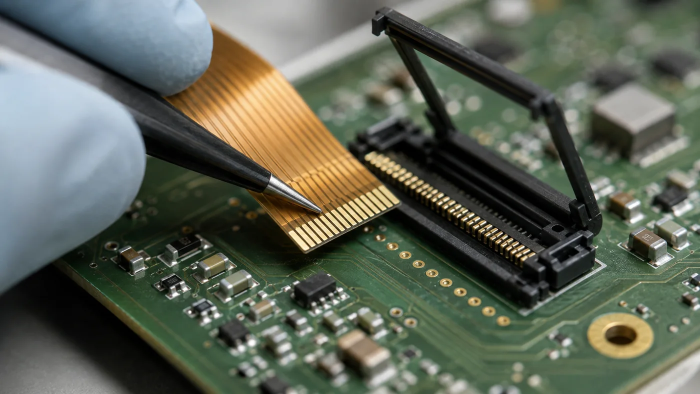
Unlike the 3.5-inch decision, where the resolution jump usually forces a change from a serial interface to a parallel one, both of these panels normally arrive with the same arrangement: a 24-bit RGB parallel interface on a 40-pin flexible printed circuit tail, a timing controller with no frame memory, and a host that must supply continuous pixel timing and hold the image itself.
That similarity is genuinely useful. A carrier board designed around one can often be reused for the other, and the mechanical FPC routing rarely changes. But it invites one specific mistake, so it is worth stating plainly: a shared pin count is not a shared pinout. Panels from different sources, and sometimes different resolutions from the same source, differ in the order of the RGB data bits, in backlight anode and cathode positions, in which pins carry the touch controller, and in whether a pin is a no-connect or a mode strap. Verify the pinout against the specific part number and ask for the interface timing table, then design the connector footprint from that document rather than from the last panel you used.
Two other interface points to settle early:
- Data width. Many hosts drive these panels as RGB565 over 16 lines rather than the full 24, which saves twelve pins and a good deal of routing. Confirm which data bits the panel expects to be tied off and how.
- Backlight drive. A 4.3-inch backlight is a string of LEDs needing a constant-current driver, not a resistor. Confirm the forward voltage and current, and confirm whether you are dimming by PWM — and if so, pick a PWM frequency that will not beat against the panel refresh or against any camera pointed at the screen.
The Platform Argument for 800×480
Here is the consideration that most often decides this in favour of the higher resolution, and it has nothing to do with image quality.
800×480 is the single most widely deployed resolution in the small-format industrial panel market, and it appears at 4.3, 5.0 and 7.0 inches. If you build a product family with a compact model, a mid model and a large model, choosing 800×480 across the range means one UI layout, one asset set, one font selection and one firmware build serve all three. Only the glass and the enclosure change.
Pick 480×272 for the compact model and you have committed to maintaining a second layout, a second set of assets and a second test matrix for the life of the product line. On a single-model product that cost is zero. On a family, it recurs at every release.
The same logic explains why stepping from 4.3 to 5.0 inches at 800×480 is often the smarter move rather than adding pixels at 4.3 inches. At 5.0 inches the same 384,000 pixels spread to about 187 PPI and a 0.135 mm pitch, so a 9.5 mm touch target is 70 pixels instead of 81 and physically identical. You get a bigger, easier interface with the same frame buffer, the same pixel clock, the same firmware and the same UI. If the enclosure has room, that is usually a better trade than fighting for density on a smaller pane of glass. Our 5.0-inch capacitive model DS-T050BWSA-02CP is a relevant module to review.
Readability, Environment and Touch
None of the above matters if the operator cannot see the screen. Two environmental points deserve attention at this size.
Brightness and reflection. Resolution does not set readability; luminance, contrast and the optical stack do. Note though that packing 2.9× the pixels onto the same glass lowers the aperture ratio, so an 800×480 panel needs more backlight current than a 480×272 panel of the same size to reach the same luminance. In daylight the dominant factor is usually reflection from the air gap between the panel and the cover glass, which is what optical bonding removes — along with the fogging risk in condensing environments.
Temperature. Liquid crystal response time lengthens substantially as temperature falls, and a panel rated to survive storage at a temperature is not necessarily a panel that starts and refreshes cleanly at it. If the product lives in an outdoor cabinet, a cold store, an unheated plant room or a vehicle, treat operating range, storage range and cold-start behaviour as three separate specifications and get all three confirmed.
On touch, the resolution correlates with what the interface demands. A 480×272 UI of large targets and physical buttons is well served by a resistive panel: inexpensive, works with heavy gloves and with water sitting on the surface. An 800×480 UI dense enough to justify the pixels usually wants projected capacitive for gestures, multi-touch and a soft keyboard, which in turn wants a specified cover glass thickness and a bonding decision.
Side-by-Side Summary
| Consideration | 480×272 | 800×480 |
|---|---|---|
| Aspect ratio | 1.765:1, near 16:9 | 1.667:1, exactly 5:3 |
| Approx. active area | 95.0 × 53.9 mm | 93.6 × 56.2 mm |
| Approx. PPI | 128 | 217 |
| Frame buffer, RGB565, single | 255 KB | 750 KB |
| Frame buffer, RGB565, double | 510 KB | 1.5 MB |
| External SDRAM usually needed | No, if the host has ~512 KB SRAM | Yes, for double buffering |
| Typical pixel clock at 60 Hz | ~9 MHz | ~33 MHz |
| Link bandwidth at 60 Hz | ~15.7 MB/s | ~46.1 MB/s |
| Signal integrity and EMC effort | Modest | Real high-speed design |
| Typical interface | 24-bit RGB parallel, 40-pin FPC | 24-bit RGB parallel, 40-pin FPC |
| List rows at a 9.5 mm touch target | About 5, full screen | About 5, plus header and footer |
| Backlight power at equal nits | Lower | Higher |
| Reuse across 5.0 and 7.0 inch | Limited | Direct, same resolution |
| Best fit | Gauges, large numerals, Latin menus, 16:9 camera feed, tight memory or power budget | Dense text and CJK, fine graphics, list-driven UI, multi-size product family |
A Decision Framework
- Draw the cutout for both active areas before committing, or accept that a later resolution change is a tooling change.
- Sketch your densest screen as a row count. Multiply your real touch target height in millimetres by the pixel pitch of each candidate. If the answer needs more rows than 272 pixels holds, the decision is made.
- Write out the worst-case text in the final language set. Dense CJK body text or a soft keyboard points firmly to 800×480.
- Check the host's usable SRAM against 510 KB and 1.5 MB. If external SDRAM is unacceptable on this board, the memory decides for you.
- Confirm the host has a display controller and, ideally, 2D acceleration. Without acceleration, plan for a mostly static UI at 800×480.
- Ask whether a 33 MHz parallel bus is acceptable in your enclosure, alongside your radios, and to your EMC budget.
- Ask whether this is one product or a family. A family usually justifies 800×480 on maintenance cost alone.
- Check whether the enclosure could take 5.0 inches. If it can, 800×480 at 5.0 inches may beat both options at 4.3.
- Confirm the environment — brightness target, sunlight exposure, condensation risk, operating and storage temperature, cold start — and only then compare panel prices.
Common Mistakes
- Assuming two 4.3-inch panels have the same active area, and cutting the bezel to suit only one.
- Porting a 480×272 layout to 800×480 by scaling, then finding the proportions and the chrome no longer work.
- Sizing memory for a single frame buffer and adding double buffering late to cure tearing.
- Routing a 33 MHz, 28-signal RGB bus with no reference plane discipline and meeting it again at pre-compliance.
- Assuming a matching 40-pin FPC means a matching pinout.
- Driving the backlight from a resistor instead of a constant-current driver, then wondering why brightness drifts.
- Choosing 800×480 on a host with no 2D acceleration and then trying to animate the whole screen.
- Choosing 480×272 for the entry model of a product family and maintaining two UI layouts forever.
- Treating storage temperature range as if it were an operating range.
Our 4.3-Inch and 5.0-Inch Options
Two of our modules cover the situations customers arrive with most often at this size. Confirm every figure against the current datasheet before you design; the table below is a starting point for a conversation, not a specification.
| Model | Size | Aimed at | Resolution | Brightness | Operating temperature | Interface | Touch |
|---|---|---|---|---|---|---|---|
| DS-T043BWSWA-02 | 4.3″ | Wide-temperature deployment: outdoor cabinets, cold storage, vehicle and unheated plant | 800×480 | 900 cd/m² | −30 to 80 °C | RGB 24-bit, 40-pin | No TP |
| DS-T050BWSA-02CP | 5.0″ | Sizing up without changing the UI: capacitive touch with an optically bonded stack for sunlight and condensation | 800×480 | 900 cd/m² | −20 to 70 °C | RGB 24-bit, 40-pin | PCAP / CTP |
If you are weighing 4.3 inches against 5.0 inches, send the internal dimension you have available in the enclosure along with the layout you have in mind. That one measurement usually resolves the question faster than a specification comparison does.
On the figures in this article. Pixel densities, frame buffer sizes and bandwidths are arithmetic from the resolution and are reliable. Active areas, pixel pitches and pixel clocks are typical industry values that vary slightly between glass sources and with the blanking intervals a given panel specifies — treat them as planning figures and confirm against the datasheet for the part you select. Everything specific to an individual module — brightness, temperature range, interface, touch type, pinout, lifecycle — must come from that module's current datasheet. Ask us for it.
FAQ: Choosing a 4.3-Inch TFT LCD Resolution
Can I swap a 480×272 panel for an 800×480 panel of the same size?
Rarely as a drop-in. The active area differs by about 1.4 mm in width and 2.3 mm in height, so the bezel cutout usually needs to change. The pinout may differ even at the same 40-pin count, the pixel clock rises from roughly 9 MHz to roughly 33 MHz, and the frame buffer grows from 255 KB to 750 KB. Treat it as a redesign of the display subsystem, not a substitution.
How much RAM do I need for an 800×480 display?
750 KB for one frame buffer at 16 bits per pixel, or about 1.5 MB double-buffered, before your application uses anything. That exceeds the internal SRAM of most microcontrollers, so double-buffered designs at this resolution normally add external SDRAM.
Is 480×272 still a sensible choice in 2026?
Yes, for a specific kind of product: a single-model device with a gauge, numeral and menu interface in Latin script, a tight memory budget, a modest EMC allowance and no requirement for dense text. It keeps the whole display subsystem simple. It becomes the wrong answer as soon as the UI is list-driven, carries CJK body text, or has to be shared with larger models in a family.
Why would I choose 5.0 inches at 800×480 over 4.3 inches at 800×480?
The pixel count, frame buffer, pixel clock, firmware and UI layout are identical, but the pixels are spread over more glass, so every touch target and every character becomes physically larger — about 187 PPI instead of 217. If the enclosure has room, it is a straightforward usability gain for no software change.
Does the higher resolution need more backlight power?
Generally yes. Fitting 2.9 times as many pixels onto the same glass means more TFT structures and more black matrix between the apertures, lowering the aperture ratio, so the backlight must drive harder to reach the same luminance. Budget for it in both the power and the thermal calculation.