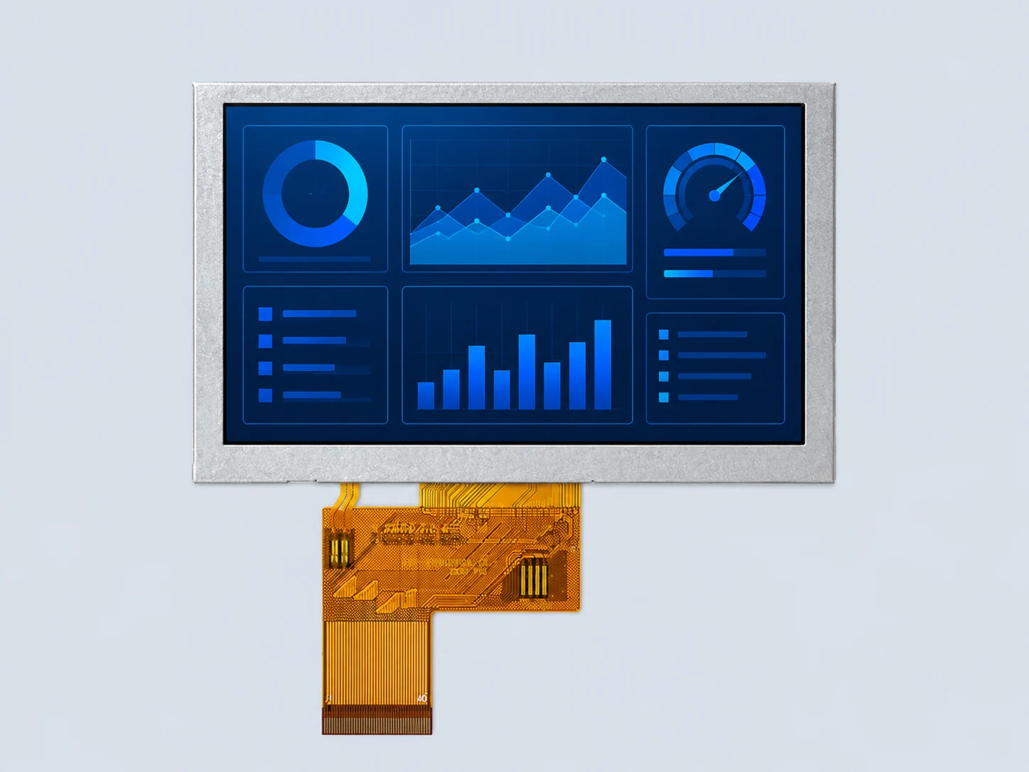
800×480 IPSNo TP
DS-T050BWSA-02
1000-nit RGB, without touch
Review the no-touch configuration when your host can drive native 800×480 RGB and the published −20 to 70 °C operating range fits the project.
View specifications and drawing →One resolution. Three different configurations. Compare native RGB modules with 1000-nit luminance, a wider operating range, or a 900-nit optically bonded PCAP assembly.
For OEM equipment integration. These are display modules, not finished HDMI monitors or controller-board kits.
All three published options use a 5-inch 800×480 IPS panel and a 24-bit RGB, 40-pin display connection. Select the exact model suffix before reviewing the host, touch path and enclosure.
| Model | Panel / resolution | Luminance | Display interface | Touch / bonding | Operating range |
|---|---|---|---|---|---|
| DS-T050BWSA-02 | 5.0 inch IPS 800×480 | 1000 cd/m² | RGB 24-bit, 40-pin | No TP Not specified | −20 to 70 °C |
| DS-T050BWSWA-02 | 5.0 inch IPS 800×480 | 1000 cd/m² | RGB 24-bit, 40-pin | No TP Not specified | −30 to 80 °C |
| DS-T050BWSA-02CP | 5.0 inch IPS 800×480 | 900 cd/m² | RGB 24-bit, 40-pin | PCAP Optical bonding | −20 to 70 °C |
No TP means no integrated touch panel is listed. Bonding is not specified for the two no-touch configurations. Luminance describes the listed module, not a guaranteed result after adding an unreviewed cover lens or touch stack.
DS-T050BWSA-02
Review the no-touch configuration when your host can drive native 800×480 RGB and the published −20 to 70 °C operating range fits the project.
View specifications and drawing →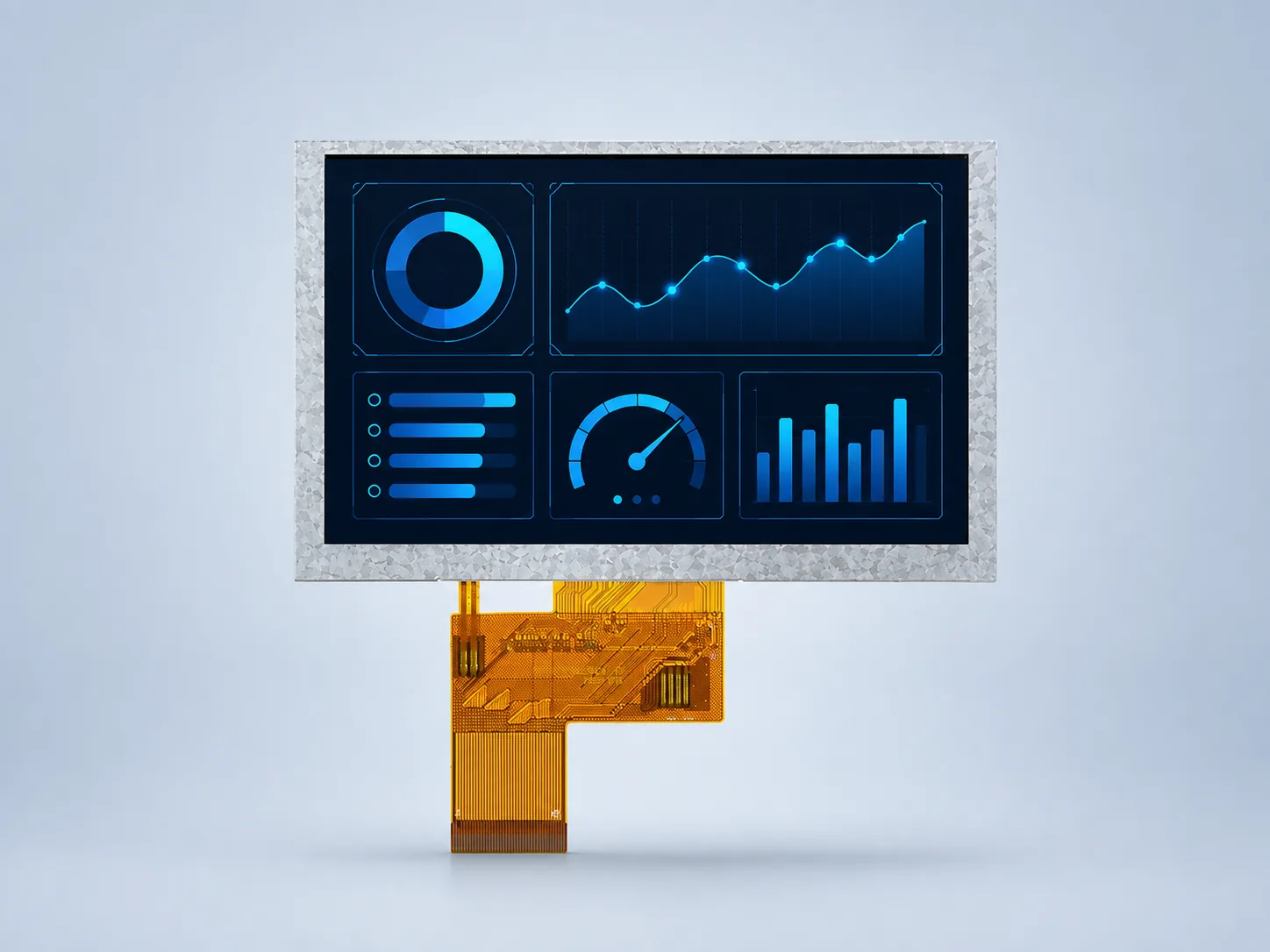
DS-T050BWSWA-02
Compare this no-touch variant when the required operating range extends to −30 or 80 °C. Confirm cold-start behavior and enclosure temperature with the exact sample.
View specifications and drawing →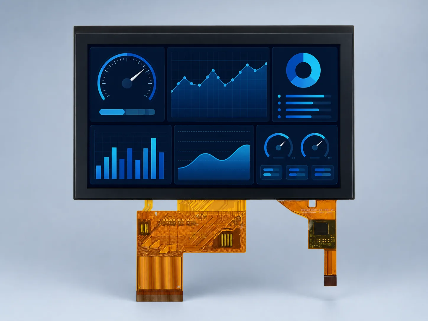
DS-T050BWSA-02CP
Review the separately documented PCAP assembly when integrated touch and optical bonding are needed. Its published outline and luminance differ from the no-touch modules.
View specifications and drawing →Product images are visual references. Use the approved drawing for geometry, tolerances and FPC keep-out areas.
Identify the processor or board output, pixel timing, data mapping and power sequence. Request the exact module pinout and backlight electrical conditions before designing a cable.
Review RGB timing →The CP model lists an ST1633i touch controller, but the RGB display connection is not the touch interface. Request the current touch-controller connection and configuration documents. Glove and wet operation require project-specific validation.
Plan PCAP integration →Compare the module operating range with conditions inside the equipment. For outdoor-facing projects, review reflected light, the cover lens and the complete assembly instead of treating a nit value as a sunlight-readability guarantee.
Review the optical requirements →| Model | Active area (W×H) | Outline (W×H×D) | Reference drawing |
|---|---|---|---|
| DS-T050BWSA-02 | 108.00×64.80 mm | 120.70×75.80×2.85 mm | Review DS-T050BWSA-02 drawing |
| DS-T050BWSWA-02 | 108.00×64.80 mm | 120.70×75.80×2.85 mm | Review DS-T050BWSWA-02 drawing |
| DS-T050BWSA-02CP | 108.00×64.80 mm | 123.26×80.06×4.30 mm | Review DS-T050BWSA-02CP drawing |
The optically bonded PCAP assembly has a different published outline. Matching width, height or pin count alone still does not establish a drop-in replacement; compare the controlled drawings, FPC contact side, cable route and enclosure clearances.
Use the LCD replacement review workflow →Source: the published model specification tables and company-provided DISEA standard TFT LCD module list, DS series 2026 V2.1. The public catalog is a summary, not an approved model-specific datasheet, pinout or test report.
Include the exact model, host output, enclosure constraints, viewing environment, touch requirement, sample quantity and expected demand. Current document revision, sample availability and commercial terms are confirmed during review.
Send project details through the enquiry form. Follow up with authorized drawings or files by email or agreed WhatsApp contact; the form does not accept attachments.
No. DS-T050BWSA-02 and DS-T050BWSWA-02 are listed as No TP. DS-T050BWSA-02CP is the separately documented PCAP and optical-bonding assembly.
The published display interface is RGB 24-bit, 40-pin. A host with only HDMI or LVDS needs a separately evaluated conversion path; these are not advertised as plug-and-play monitor kits.
No. Confirm the current pinout, timing, power requirements, connector orientation, FPC routing and approved mechanical drawing for both the host and exact module. A shared pin count does not establish compatibility.
No. The public catalog is a summary reference, and the product-page drawings are reference images. Request the current model-specific datasheet and approved drawing before design-in; confirm sample availability and commercial terms during the project review.
Start with your existing part number, drawing or requirements. Confirm the current datasheet and approved drawing before design-in.
Need more UI area? Compare 7-inch LVDS modules or return to the size selection guide.