Short Answer
On a 3.5-inch panel, 320×240 gives you roughly 114 pixels per inch and a 150 KB frame buffer, which an ordinary microcontroller can drive over SPI or an 8080 parallel bus using a driver IC that holds the image for you. 640×480 gives you roughly 229 PPI and a 600 KB frame buffer, which almost always means an RGB or MIPI interface, external SDRAM, and a host that redraws every frame itself. Choose 320×240 unless something on the screen genuinely fails at 114 PPI — dense CJK text, fine engineering curves, small photographic detail or a close viewing distance. If nothing fails, the extra resolution costs you money, power and schedule for no user-visible gain.
The Two Resolutions in Numbers
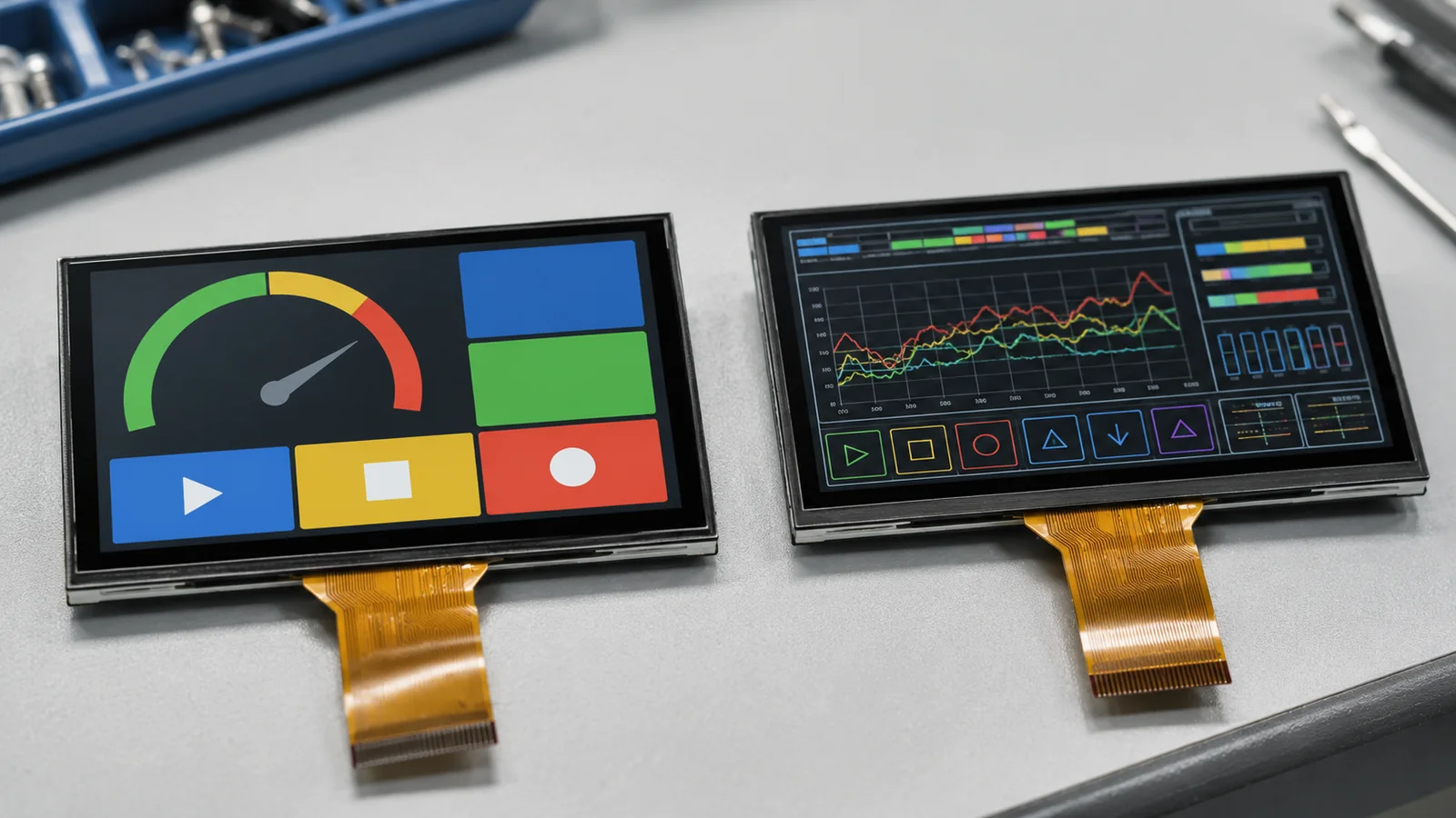
A 3.5-inch diagonal in 4:3 format is about 71 mm wide and 53 mm tall. Put 320×240 on it and the diagonal pixel count is 400, which divided by 3.5 inches gives about 114 PPI. Put 640×480 on the same glass and the diagonal pixel count is 800, giving about 229 PPI. Each individual pixel drops from roughly 0.22 mm square to roughly 0.11 mm square.
There is a third option that gets overlooked. Many 3.5-inch panels ship at 320×480 in a 2:3 portrait format, which lands at about 165 PPI. If your interface can carry it and your layout is portrait, it often resolves the argument on its own.
| Resolution | Aspect | Total pixels | Approx. PPI | Approx. pixel pitch |
|---|---|---|---|---|
| 320×240 (QVGA) | 4:3 | 76,800 | 114 | 0.22 mm |
| 320×480 (HVGA) | 2:3 | 153,600 | 165 | 0.15 mm |
| 640×480 (VGA) | 4:3 | 307,200 | 229 | 0.11 mm |
For reference, a current smartphone sits somewhere north of 400 PPI, but it is held about 300 mm from the eye. An instrument panel read at 500 to 700 mm has a much easier job. Resolution requirements are a function of viewing distance, not of what your phone happens to do.
What the Extra Pixels Actually Buy
Text, and Especially CJK Text
Latin characters stay legible down to a very small bitmap. Chinese, Japanese and Korean glyphs do not: a dense character needs roughly 16×16 pixels to be identifiable and closer to 24×24 to be comfortable to read for any length of time. At 114 PPI a 16-pixel glyph is about 3.6 mm tall, which is workable at arm's length and tiring beyond it. At 229 PPI the same 3.6 mm glyph gets 32 pixels and renders cleanly with anti-aliasing.
This is the single most common reason a project genuinely needs 640×480. If the UI carries multi-line CJK body text, dense parameter lists or a soft keyboard, count the glyphs before you count anything else.
Curves, Waveforms and Fine Line Work
Diagonal and curved lines are where low resolution shows first. A trend graph, an ECG-style trace, a rotating dial needle or a CAD-style outline all reveal stair-stepping at 114 PPI that no amount of anti-aliasing fully hides. If the operator is reading a shape rather than a number, resolution matters.
Photographic and Camera Content
If the panel displays a camera preview, a scanned image or product photography, 320×240 is a hard ceiling. This is not a subtle preference; a QVGA preview looks like a QVGA preview.
Where the Extra Pixels Buy Nothing
Large numeric readouts, status icons, bar graphs, menu lists in Latin script, and anything read from more than half a metre away all look identical at both resolutions. A great many industrial and instrumentation UIs fall entirely into this category, and paying for VGA to display four large digits is a straightforward waste.
What the Extra Pixels Cost
Frame Buffer Memory
At 16 bits per pixel in RGB565, which is the normal choice for embedded UI, the arithmetic is unforgiving:
- 320×240 × 2 bytes = 153,600 bytes, about 150 KB.
- 320×480 × 2 bytes = 307,200 bytes, about 300 KB.
- 640×480 × 2 bytes = 614,400 bytes, about 600 KB.
Double-buffer to eliminate tearing and every figure doubles: 300 KB, 600 KB and 1.2 MB respectively. Very few microcontrollers carry 1.2 MB of usable internal SRAM. In practice a double-buffered VGA design means adding external SDRAM, which brings its own layout, EMC, cost and lead-time consequences.
Bandwidth and Pixel Clock
Refreshing at 60 Hz in RGB565, the display link has to carry:
- 320×240: about 9.2 MB/s, with a typical pixel clock near 6.4 MHz once blanking is included.
- 640×480: about 36.9 MB/s, with the standard VGA pixel clock of 25.175 MHz.
That is the display link alone. Your graphics engine also has to write the frame, and a full-screen redraw at VGA moves four times the data of a QVGA redraw. On a part without a 2D acceleration block, the difference between a UI that feels instant and one that visibly wipes down the screen is usually here.
Backlight Power
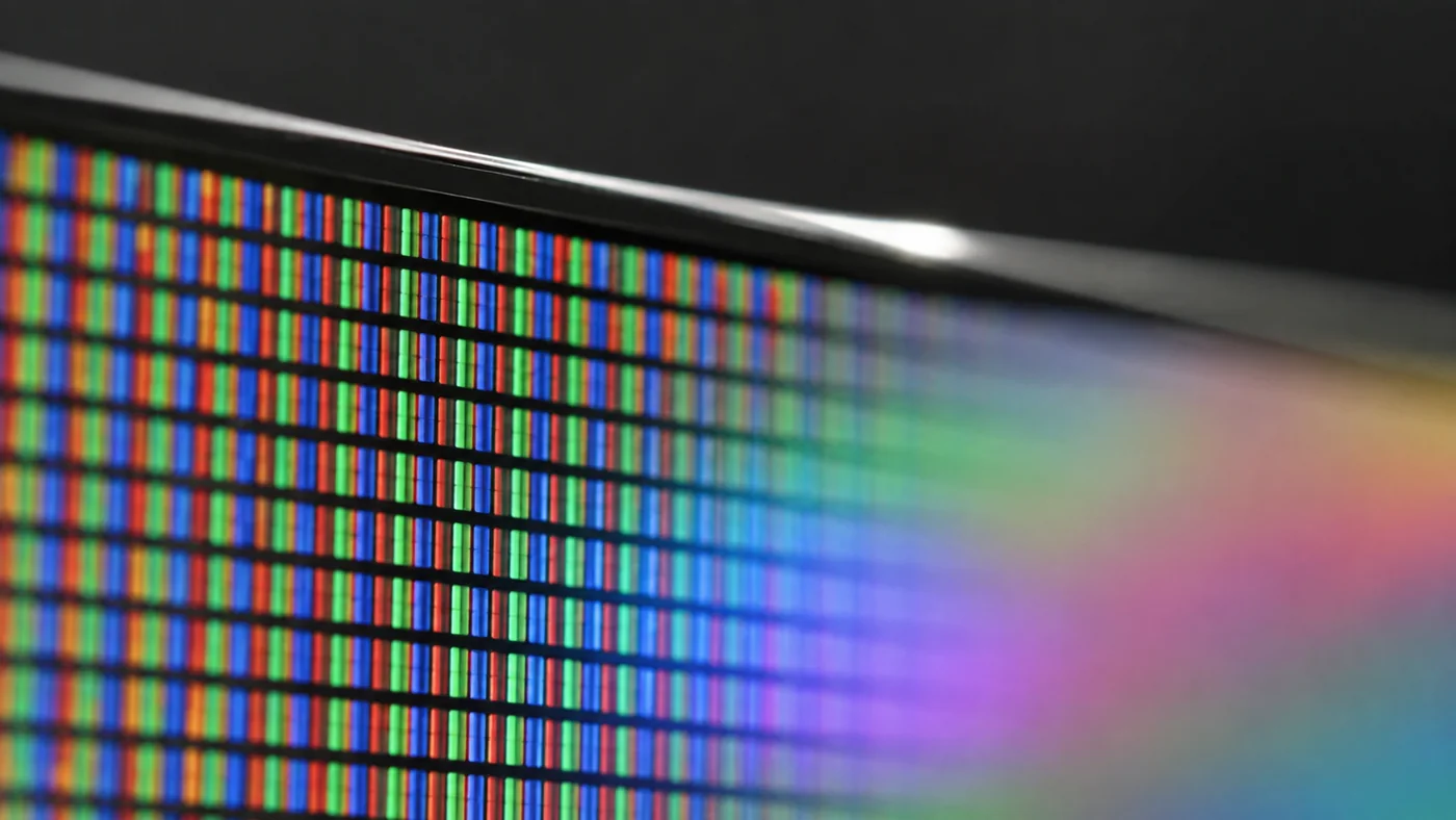
This one surprises people. Squeezing four times as many pixels onto the same glass means four times as many TFT switches and four times as much black matrix between the apertures, so the aperture ratio falls. A higher-resolution panel of the same size and the same target luminance therefore needs more backlight current, not less. On a battery-powered or thermally constrained product this can matter more than the controller cost.
Interface and Driver IC: The Real Fork in the Road
Resolution does not merely change a number in the datasheet. At this size it changes the entire class of interface, and that is what reshapes your schematic.
The 320×240 World
QVGA panels at 3.5 inches almost always ship with a driver IC that contains its own graphics RAM — the ILI9341 and HX8357 families are the ones you meet most often. Because the image lives on the panel side, your host only has to send the pixels that changed. That single fact is what makes SPI and 8080-series parallel viable:
- 4-wire SPI: four or five signals, trivial routing, no EMC drama. Fine for menus, gauges and partial updates. Full-screen animation over SPI is slow and you will feel it.
- 8080 / 6800 parallel, 8 or 16 bit: considerably faster, still driven from a general-purpose MCU with an external memory controller. This is the classic industrial QVGA configuration.
A part in the class of an STM32F103 or similar mid-range MCU, with no dedicated display peripheral and no external RAM, will drive this comfortably.
The 640×480 World
VGA panels at 3.5 inches generally carry a timing controller with no frame memory. The host must generate continuous pixel timing and hold the entire image itself. That implies:
- An RGB parallel interface, typically 16, 18 or 24 data lines plus HSYNC, VSYNC, DE and the pixel clock — a wide, fast, length-sensitive bus.
- Or MIPI DSI, which reduces the pin count to a couple of differential pairs but requires a host with a DSI block.
- A host with a display controller such as an LTDC block, plus 2D acceleration if you want responsive redraws.
- External SDRAM, in almost every double-buffered case.
You have moved from a mid-range MCU to a high-end MCU or an application processor, from a four-layer board to a carefully stacked four or six layer board with matched-length routing, and from a straightforward EMC story to one that needs attention. The panel price difference is often the smallest line in the change.
| Consideration | 320×240 | 640×480 |
|---|---|---|
| Approx. PPI | 114 | 229 |
| Frame buffer, RGB565, single | 150 KB | 600 KB |
| Frame buffer, RGB565, double | 300 KB | 1.2 MB |
| Typical pixel clock at 60 Hz | ~6.4 MHz | ~25.2 MHz |
| Link bandwidth at 60 Hz | ~9.2 MB/s | ~36.9 MB/s |
| Frame memory on driver IC | Usually yes | Usually no |
| Common interfaces | SPI, 8080/6800 parallel | RGB parallel, MIPI DSI |
| Typical host class | Mid-range MCU | High-end MCU or application processor |
| External SDRAM needed | Rarely | Usually |
| PCB and EMC effort | Low | Moderate to high |
| Backlight power at equal nits | Lower | Higher |
| Panel availability at 3.5 inch | Very broad | Narrow |
| Best fit | Gauges, menus, status, Latin text, arm's length or further | Dense CJK text, fine curves, camera preview, close viewing |
The Availability Point Nobody Costs In
320×240 at 3.5 inches is one of the highest-volume small-panel configurations in the industry, with a deep bench of interchangeable parts and driver ICs. 640×480 at 3.5 inches is a niche. Fewer glass sources, fewer second sources, longer lead times, and a materially higher chance of an end-of-life notice landing in the middle of a seven-year product life.
For a consumer product with an eighteen-month life this is noise. For an industrial instrument you intend to build for a decade, it is a design risk that belongs in the decision alongside the pixel count. Ask for the lifecycle commitment in writing before you design around a niche resolution.
Touch, Cover Glass and Optical Stack
Resolution and touch technology are separate choices, but they correlate in practice. A QVGA gauge-and-menu interface with large targets works perfectly well with a resistive touch panel, which is cheap, glove-friendly and immune to water on the surface. A VGA interface dense enough to justify the pixels usually implies small targets, gestures and a soft keyboard, which points to projected capacitive.
If the display sits behind cover glass in sunlight or in a condensing environment, the optical stack matters more than the resolution. Air bonding leaves an air gap that reflects at each interface and can fog; optical bonding fills the gap and improves contrast outdoors, at some cost in reworkability. Our capacitive-touch 3.5-inch model DS-T035SGV-01CP is the option we point customers to when the front stack is the constraint rather than the pixel count.
A Decision Framework You Can Run in Ten Minutes
- Measure the real viewing distance. Not the distance at your desk — the distance in the installed position, with the operator standing where they will actually stand.
- Count the worst-case glyphs. Write out the densest screen in the final language set. If it contains CJK body text, small-point labels or a soft keyboard, note it.
- Identify the finest graphical element. A one-pixel trend line, a dial needle, a small icon with internal detail. Mock it up at both resolutions before deciding.
- Check your host's memory against the table above. Include double buffering if you want tear-free animation, and include your application's own RAM needs.
- Check the interface your host actually has. No LTDC or DSI block means VGA is a processor change, not a panel change.
- Check the power and thermal budget. Higher resolution at equal brightness means more backlight current.
- Check the required product lifetime against panel availability at the resolution you are considering.
- Only then compare panel prices. By this point the panel price is usually not the deciding line.
Run steps 2 and 3 with a real mock-up rather than an opinion. Render the densest screen at 320×240 and at 640×480, print both at the physical panel size, tape them to the enclosure and look at them from the operating position. That fifteen-minute exercise settles more arguments than any amount of specification review.
Common Mistakes
- Choosing the resolution before choosing the host, then discovering the MCU has no display controller.
- Budgeting a single frame buffer and then adding double buffering late to fix tearing, with no memory left.
- Judging legibility on a desktop monitor at 100% zoom instead of at the panel's physical size and real viewing distance.
- Assuming a higher-resolution panel of the same size draws the same backlight power.
- Specifying VGA for a UI that is four large digits and three status icons.
- Specifying QVGA for a UI that has to render multi-line Chinese body text.
- Routing a 25 MHz RGB bus like a 6 MHz one and meeting EMC problems at certification.
- Designing a ten-year industrial product around a niche resolution with a single glass source.
Our 3.5-Inch Options
Two of our 3.5-inch modules cover the situations customers most often arrive with. Confirm every figure against the current datasheet before you design; the summary below is a starting point for a conversation, not a specification.
| Model | Aimed at | Resolution | Brightness | Operating temperature | Interface | Touch |
|---|---|---|---|---|---|---|
| DS-T035HLWSA-01 | Wide-temperature deployment: outdoor cabinets, cold storage, vehicle and unheated plant | 320×240 | 900 cd/m² | −30 to 85 °C | RGB 24-bit, 54-pin | No TP |
| DS-T035SGV-01CP | Front-of-glass performance: capacitive touch with an optically bonded stack for sunlight and condensation | 640×480 | 320 cd/m² | −20 to 70 °C | RGB 24-bit, 54-pin | PCAP / CTP |
If your application sits at the edge of the temperature envelope, the cold-start behaviour of the liquid crystal and the backlight matters more than anything on this page — response time lengthens sharply below the rated minimum and a panel that survives storage at a temperature is not the same as a panel that starts at it. If the constraint is instead reflection, contrast in daylight or fogging behind cover glass, the bonding method is the lever to pull.
On the figures in this article. Pixel densities, memory sizes and bandwidths here are arithmetic from the resolution and are reliable. Pixel clocks are typical values that vary with the blanking intervals your panel specifies. Everything specific to an individual module — brightness, temperature range, interface, touch type, lifecycle — must come from that module's current datasheet. Ask us for it.
FAQ: Choosing a 3.5-Inch TFT LCD Resolution
Is 320×240 too low resolution for a modern product?
Not for a great many industrial and instrumentation products. At 114 PPI and a viewing distance of half a metre or more, large numerals, status icons, bar graphs and Latin menu text all render cleanly. It becomes limiting when the screen carries dense CJK text, fine curves or photographic content, or when the operator is very close to the glass.
Can I drive a 640×480 3.5-inch panel over SPI?
In practice, no. A VGA panel at this size generally has no frame memory on the driver IC, so the host must supply continuous pixel timing over an RGB or MIPI interface. Even where a serial path exists, moving 36 MB/s of pixel data per second over SPI is not a realistic design.
How much RAM do I need for a 640×480 display?
600 KB for one frame buffer at 16 bits per pixel, or 1.2 MB double-buffered, before your application uses a single byte. Very few microcontrollers offer that internally, so most VGA designs at this size add external SDRAM.
Does a higher-resolution panel use more power?
Usually yes, for two reasons. The interface and graphics engine move four times the data, and the aperture ratio falls because more of the glass is occupied by TFT structures and black matrix, so the backlight has to work harder to reach the same luminance.
What about 320×480 as a middle option?
It is a genuine middle ground at roughly 165 PPI and a 300 KB frame buffer, and it is well supported at 3.5 inches. The catch is the 2:3 portrait aspect ratio, which suits a tall layout and fits a landscape one badly. If your layout is portrait, evaluate it seriously before jumping to VGA.