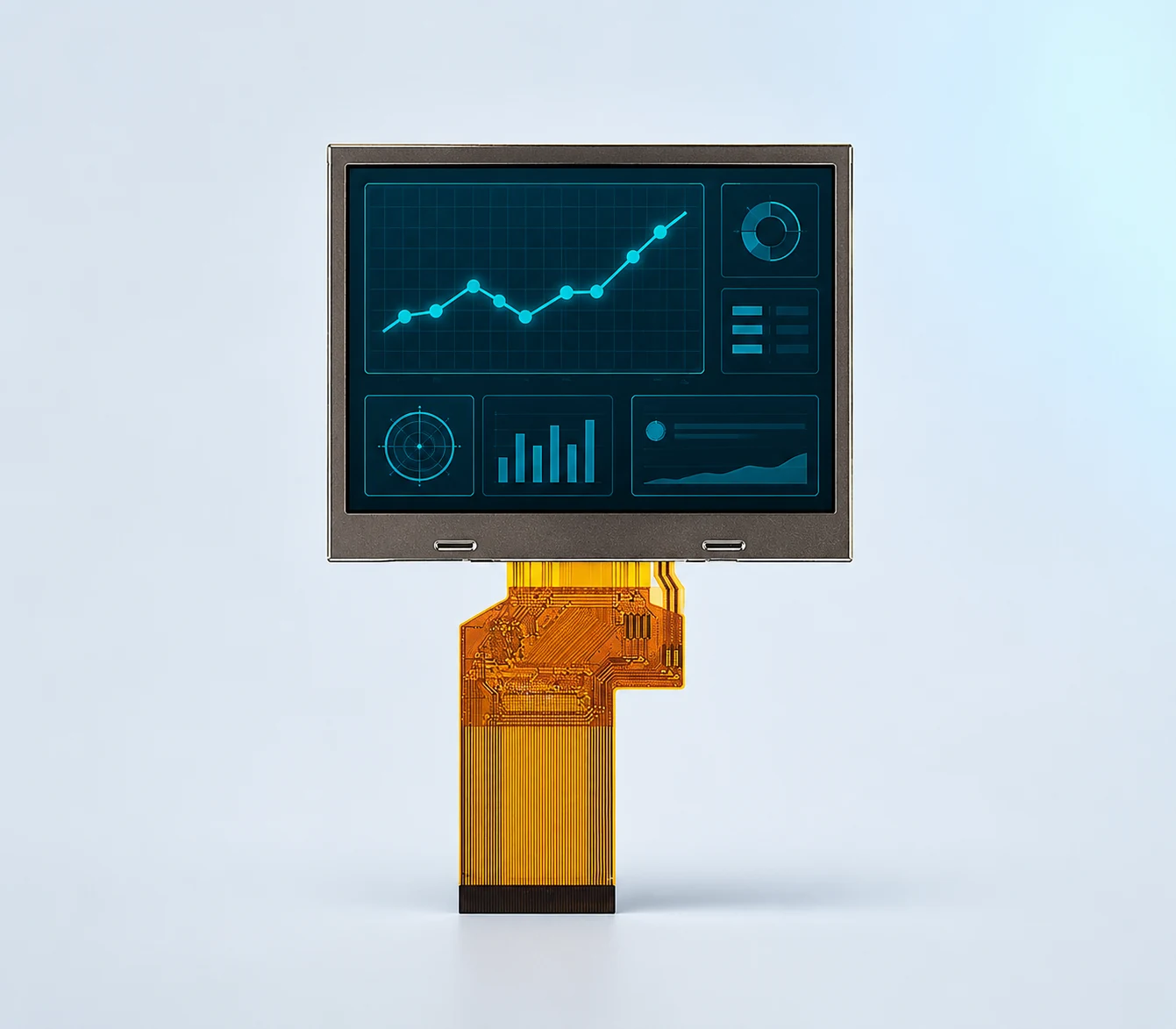
3.5 inchIPS
DS-T035HLWSA-01
320×240 · 900 cd/m²
RGB 24-bit, 54-pin
No TP
Select a small TFT LCD module for handheld instruments by the real UI, native host output and available enclosure space. The published shortlist below uses RGB; compare the exact touch assembly and operating-state power requirements before requesting samples.
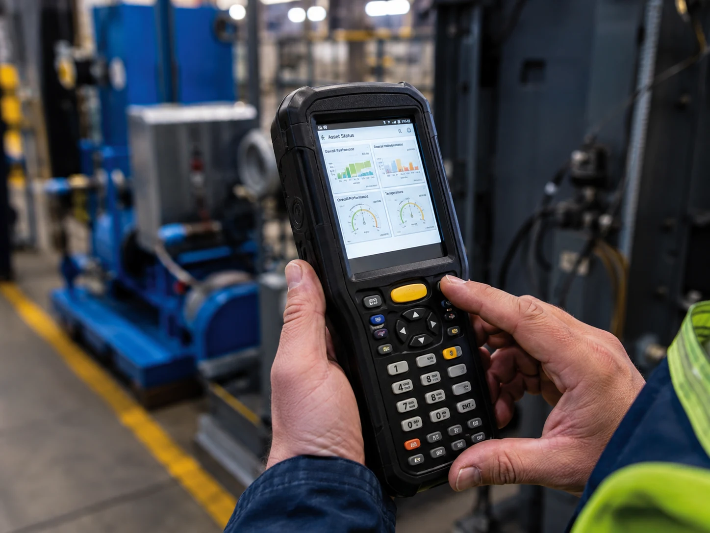
Battery power, backlight duty, front-stack thickness, connector access and operator input drive the shortlist. Compare the actual luminance and touch configuration rather than transferring one small-screen specification to another. Impact and drop performance require complete-device testing.
| Model | Size / resolution | Panel / luminance | Display interface | Touch / bonding | Operating range | Why review it |
|---|---|---|---|---|---|---|
| DS-T035HLWSA-01 | 3.5 inch 320×240 | IPS 900 cd/m² | RGB 24-bit, 54-pin | No TP | −30 to 85 °C | 3.5-inch 320×240 IPS RGB no-touch option with 900 nits |
| DS-T035SGV-01CP | 3.5 inch 640×480 VGA | IPS 320 cd/m² | RGB 24-bit, 54-pin | PCAP / CTP Optical bonding | −20 to 70 °C | 3.5-inch 640×480 bonded PCAP at 320 nits; different stack and power target |
| DS-T043BWSWA-02 | 4.3 inch 800×480 | IPS 900 cd/m² | RGB 24-bit, 40-pin | No TP | −30 to 80 °C | 4.3-inch 800×480 IPS RGB no-touch option with −30 to 80 °C operation |
Luminance belongs to the exact listed configuration. It is not a finished-system sunlight-readability, sealing, EMC or safety certification. “No TP” means no integrated touch panel is documented.
RGB 24-bit, 54-pin
No TP
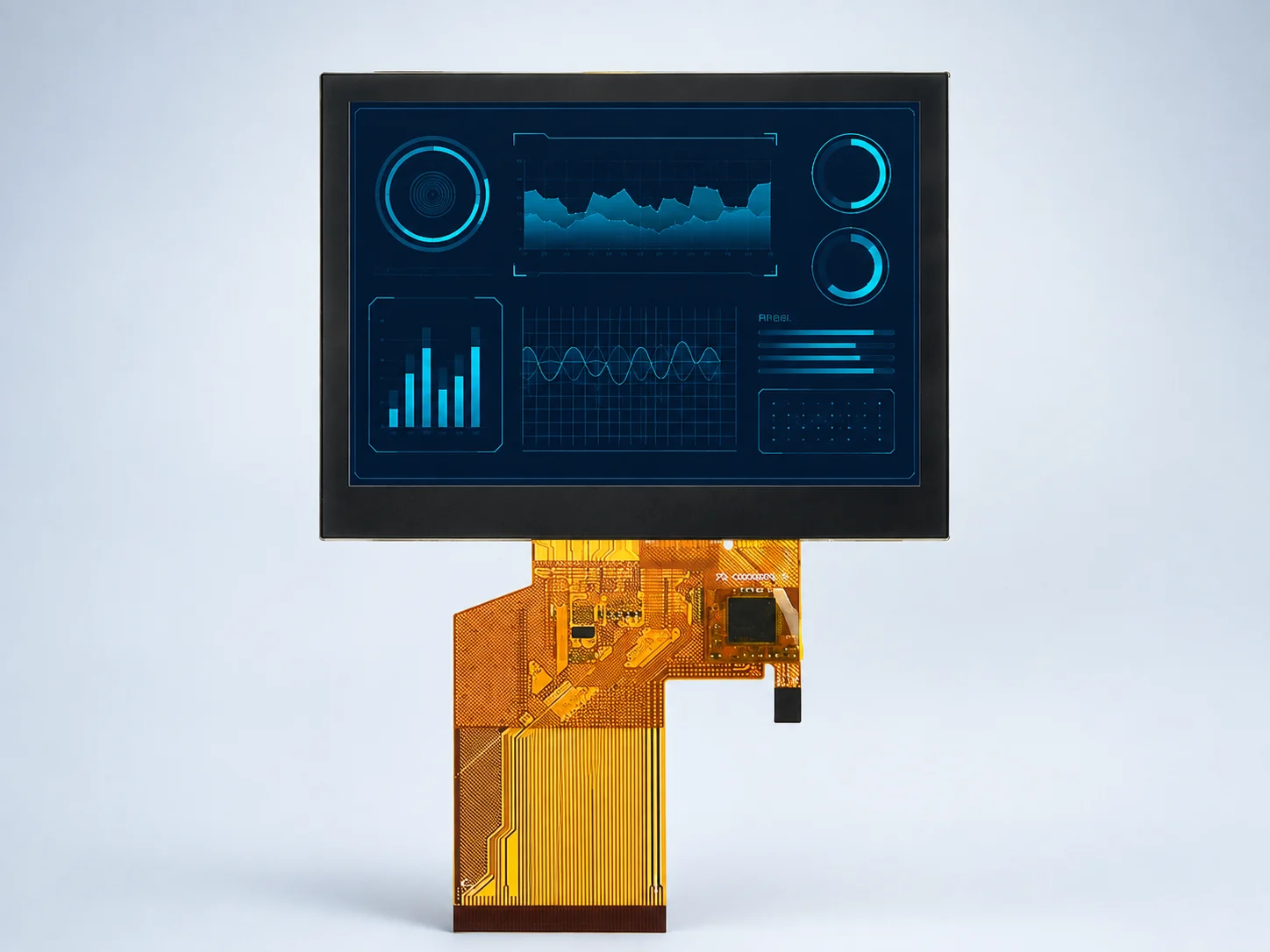
RGB 24-bit, 54-pin
PCAP / CTP · Optical bonding
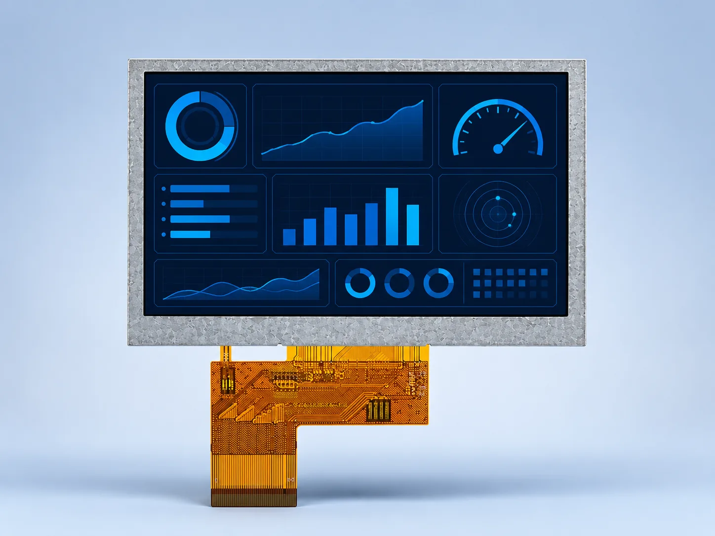
RGB 24-bit, 40-pin
No TP
For a handheld instrument, a small diagonal does not establish battery life, touch behavior or mechanical fit. Use the published shortlist to choose what to evaluate, then confirm the operating states and complete assembly that the sample must reproduce.
On smaller screens, scroll the table horizontally to compare all three columns.
| Design decision | Bring to the review | Confirm on the sample |
|---|---|---|
| Battery and backlight | Battery target, available rails, time spent active or idle, brightness settings and wake-up behavior. | Measure the display and backlight contribution in the actual operating states. A luminance rating is not a power-consumption specification. Plan the control method using the dimming guide. |
| UI density and host output | Representative UI screens, required text size, native resolution and the processor’s available display output. | Check the exact timing, pin mapping, memory and update behavior. The three candidates above use RGB; an SPI- or MIPI-only host needs a separate interface review, not an assumed direct connection. |
| Grip and operator input | One- or two-handed use, physical buttons, exact glove or stylus, and the intended orientation. | Review touch reach, edge controls and unintended presses on the assembled front panel. Use the PCAP versus resistive sample plan when touch is needed. |
| Outline and FPC route | Enclosure opening, mounting points, available stack height, connector access and cable route. | Compare the drawing and physical sample; record assembly clearance and cable constraints. Use the FPC review guide. A module temperature range does not establish finished-device drop or sealing performance. |
If physical buttons are retained, compare the no-touch DS-T035HLWSA-01 at 320×240 with DS-T043BWSWA-02 at 800×480. If the task needs touch and a denser compact UI, review DS-T035SGV-01CP, a separate 640×480 bonded-PCAP configuration. A shared 3.5-inch diagonal does not preserve UI layout, cable mapping or front-panel depth. Request the current compact-PCAP documents if that input path fits. No listed luminance establishes battery runtime or measured power consumption.
If the host output is uncertain, send the processor or board reference and its display-connection information. If the project replaces a screen, include the old part number and drawing rather than only its diagonal. The datasheet-reading guide helps identify the connection and mechanical pages to compare.
The form preselects Handheld Instrument and provides editable prompts for the battery, host, input and enclosure. Send drawings by email or WhatsApp; the web form accepts text only. No measured power, battery-life or drop-test results are asserted here. Checklist updated October 14, 2026.
For a small TFT LCD in a handheld device, state the UI resolution, host RGB output, enclosure opening, input method and operating-state power target. Include sleep, startup and active-use conditions so the candidate module and any touch assembly can be reviewed against the actual instrument.
Resolution, luminance and touch describe different modules.
Explore this selection path →Check UI fit and exact native RGB timing.
Explore this selection path →Verify pixel clock, porches, polarity and host mapping.
Explore this selection path →Start with the most demanding real UI and the native display output available on the handheld host. The listed candidates use parallel RGB; they are not SPI shields or HDMI kits. Decide whether the project needs the 3.5-inch QVGA no-touch module, a separate VGA bonded-PCAP configuration, or the 4.3-inch 800×480 no-touch option. Compare the approved outline and FPC route, then budget the host, display, touch and backlight in active, dimmed and standby states. Published luminance is not a power or battery-runtime specification; obtain electrical data and measure the intended configuration.
Compare 320×240 and 640×480 around readability, memory, bandwidth and physical fit.
Review 3.5-inch resolutions →Match the display link and update rate to the processor, memory and available interface hardware.
Compare TFT interfaces →Verify connector position, bend region, pin mapping, retention and controlled drawings.
Review FPC customization →Brightness, backlight, FPC, interface, touch, cover glass, optical bonding and driver-board options should be considered only where the project requires them.