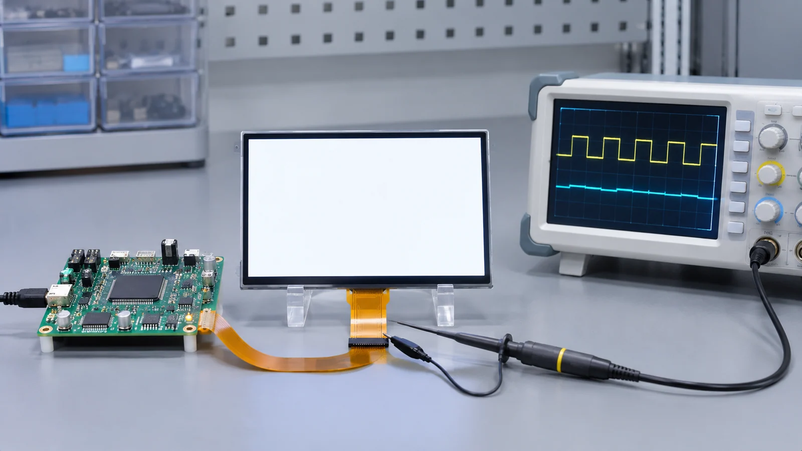
The module is powered, the backlight lights, and the screen is a flat white rectangle. It is one of the most common bring-up outcomes, and it is easy to chase in the wrong direction because the backlight makes it look as if the display is almost working. The backlight has its own supply, enable and dimming. The image comes from a different chain.
The interface troubleshooting guide gives the general eight-step workflow and a symptom table that lists a white or uniform bright screen. This guide covers only the white-screen branches in more detail and does not repeat that workflow. The tables are starting points to confirm by measurement, not diagnoses.
What a lit white screen proves, and what it does not
| Path | What it contains | What a lit white screen tells you |
|---|---|---|
| Backlight path | LED supply, backlight enable, dimming input, LED driver and LEDs | These work well enough to light the panel |
| Image path | Logic and analog supplies, reset, the video or command stream, initialization, and interface configuration | Nothing yet. White can be the panel's state with no valid image data |
Orient Display, a display vendor, describes a white screen as a default output state of the driver IC, and notes that if the panel is powered and the backlight works, the hardware is likely operational and the initialization sequence may have been incomplete, out of order or mistimed. It calls releasing reset too early, or starting video before initialization is complete, the most common cause the vendor sees in practice. It gives no numeric delays, so take those from your driver IC and module datasheets.
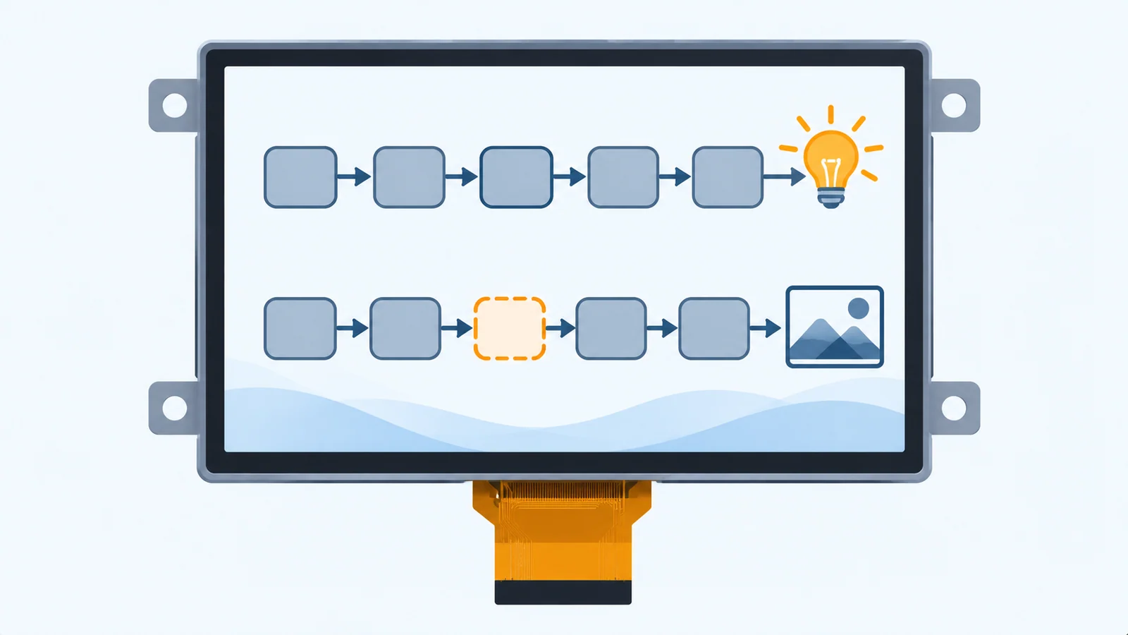
Read the white before you probe
Note exactly how the white behaves. Watch from the moment power is applied, and write down what you saw.
| What you see | Points to | Go to |
|---|---|---|
| Plain white from the moment power is applied, no change when the software starts | A missing or invalid stream or incomplete initialization are possibilities | Branches 1 to 4 |
| White until the software starts, then the picture appears | Possibly late host start-up with the backlight already on | Sequencing section below |
| A white flash at the start, then the picture | Possibly the backlight was enabled before the first valid frame | Sequencing section below |
| White that comes back repeatedly, or the host restarts | A supply dip or reset loop, including a possible backlight load on a shared rail | Branch 1 and the startup current guide |
| White with a faint or broken pattern in it, or an image in part of the screen | Possible timing, mode, mapping or signal-integrity mismatch | Branches 3 and 4 |
| White only at one temperature, cable position or voltage | Possible power, connector or timing margin issue | Branch 5 |
| White on one unit, picture on another | A sample or assembly difference | Branch 6 |
The branch table
Take the branches in order. Each one asks a single question and tells you what a yes or a no means.
| Branch | Question | If yes | If no or unknown |
|---|---|---|---|
| 1. Supplies and reset | Are all supplies at the connector valid and in the datasheet order, and is reset released only after they are valid? | Go to branch 2 | Fix the supply or reset first; a regulator can look correct with no load and collapse during panel start-up, so capture it during the power-up event |
| 2. Stream present | Does the host emit the signals the interface needs at the connector: pixel clock with DE or sync for parallel RGB, a clock pair with data for LVDS, activity on the lanes for MIPI DSI? | Go to branch 3 | The required signal has not been confirmed at the connector; check the host configuration, power and cable using a measurement appropriate to the interface |
| 3. Initialization | If the panel has a control interface (SPI, I²C or DSI commands), did the complete sequence run for this exact panel revision, and does a read-back such as an ID read succeed where the controller allows it? | Go to branch 4 | Confirm whether initialization applies and obtain the sequence for the exact module revision; check the documented commands and timing |
| 4. Configuration match | Do the stream and the panel agree on mode, polarity, bit width, lane count and timing? | Go to branch 5 | Compare the host's output settings with the datasheet row by row; see the table below |
| 5. Margins | Does the fault depend on voltage, temperature, cable length or position? | Treat it as a margin issue and test the corners | Go to branch 6 |
| 6. Substitution | Does a known-good host output, then a known-good module, change the result? | The result implicates the replaced part or its interaction with the rest of the system; investigate further | Re-check the record of what was changed |
Branch 4: what to compare, by interface
| Interface | Compare | Typical symptom of a mismatch |
|---|---|---|
| Parallel RGB | Whether the panel runs in DE mode, sync mode or either; HSYNC, VSYNC, DE and clock polarity; clock edge; bit width; porches and pixel clock (see the RGB timing guide) | White, black or an unstable picture when sync or DE is missing or inverted |
| LVDS | Bit depth, data mapping mode, data enable and clock presence (see the LVDS cable length guide) | Mismatch can cause wrong colors, an unstable picture or no valid image; check the actual host and panel |
| MIPI DSI | Lane count, video or command mode, pixel format, initialization data, low-power to high-speed move (see the MIPI lane selection guide) | White or blank when the panel is not initialized; garbage or color faults when the format disagrees |
| MCU bus or SPI | Bus width, command set, write timing and the controller's register setup (see the interface guide) | White when the controller received no valid pixel writes |
Bring the backlight up after the picture
Orient Display lists the power-on order as the logic supply, then the analog drive voltages, then reset applied and released, and then the host starting the video signal. The backlight is not in that list, and where a design requires an unseen startup, an appropriate backlight enable point should be agreed for that module and host. Many module datasheets specify when the backlight may be enabled; read yours.
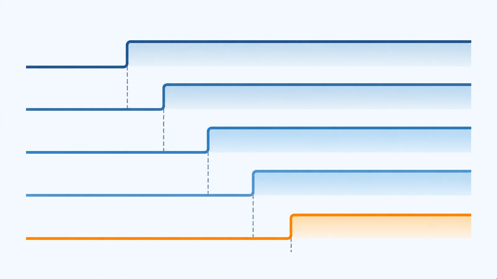
| Order | Event | Delay required before the next step | Source document |
|---|---|---|---|
| 1 | Logic supply valid | ||
| 2 | Analog and drive voltages valid | ||
| 3 | Reset applied, then released | ||
| 4 | Initialization commands, if the panel needs them | ||
| 5 | Video stream starts | ||
| 6 | Backlight enabled, at the lowest level first |
If enabling the backlight makes the host restart, a shared supply disturbance is one possible cause. A display vendor's article on this describes the backlight drawing more power and pulling the supply down, and recommends confirming that the processor actually reset and measuring the display input, the processor supply, the reset line and the dimming signal while changing brightness. The startup current and brownout guide covers that case. The dimming input's state before the host drives it also matters; see the dimming guide.
A white screen record sheet
| Item | What to record | Your entry |
|---|---|---|
| Module | Model, suffix and document revision | |
| Host and software | Board revision, firmware build and display driver version | |
| Interface | Type, mode, bit width or lanes, and the cable used | |
| How the white behaves | When it appears, whether it changes, whether it flashes, restarts or shows faint structure | |
| Supplies and reset at the connector | Voltages, order and timing, captured during power-up | |
| Stream at the connector | Which signals were present and when | |
| Initialization | Sequence version, whether it ran, read-back result if any | |
| Configuration compared | Settings checked against the datasheet, and any difference | |
| Substitutions | Known-good host or module tried, and the result | |
| Change made and result | One line per change, in order |
Keep the sheet with the software baseline. Who owns the initialization data, the driver and the sequencing code is covered in the software integration checklist. For the evidence that makes a review fast, see the sample validation checklist.
Questions to ask the supplier
- What are the required power-up and power-down sequences, with delays, for the module and its driver IC?
- What does the panel show when it has power and a backlight but no valid image data?
- Does the panel need an initialization sequence over a control interface, and is it available for this module revision?
- When may the backlight be enabled relative to the video stream, and what is its state if the dimming input is not yet driven?
- Which interface mode, polarities, bit width and timing does the panel require?
- Is there a read-back or ID register that can prove the control link works?
Send the answers with your record sheet, a supply and reset capture and your host details through a project review, so the cause is checked against a real configuration.
White screen FAQ
Why is my TFT LCD white when the backlight works?
A working backlight only proves the light path. The image path is a separate chain of logic power, reset, a valid video or command stream and a completed initialization. If any link is missing, many driver ICs fall back to a default output, which can be a plain white screen. Find out which link is missing by checking the supplies and reset at the connector, then the stream, then the configuration.
Does a white screen mean the panel is broken?
Usually not. A white screen is more often an unfinished power-up or initialization, a missing video stream, or a configuration mismatch than a damaged panel. Check it by swapping in a known-good host output or a known-good module, one at a time. Only then decide whether the module is at fault.
Why does the screen flash white at startup and then show the picture?
The backlight was switched on before the first valid frame reached the panel, so you briefly see its default state. It is a sequencing issue, not a fault. Hold the backlight off or at the lowest level until the host is sending valid frames, and follow the backlight timing in the module datasheet.
What should I check first with a MIPI DSI panel that stays white?
Check the supplies and reset order at the connector, then confirm that the initialization commands for your exact panel revision are sent, including sleep-out and display-on. After that, confirm that the host moves from low-power to high-speed output with the lane count and mode the panel expects. The supplier data record in the MIPI lane selection guide lists what to request.
Technical references
- Orient Display — LCD Power-on Process: a display vendor's description of the supply, reset and video order, and of a white screen as a default output state of the driver IC.
- CDTech — MIPI DSI power sequencing and white screen errors: a vendor article that ties white screens to supply, reset and lane timing. Its timing values are its own recommendations for its own panels, not specifications.
- DisplayModule — Why does a TFT LCD reset when the backlight brightness is increased: a vendor article on a shared supply that dips when the backlight loads it. Its figures are examples.
Related engineering guide
For a separate integration check, read Touch Coordinates Wrong After Rotation.
Send Us Your White Screen Evidence
Share the exact module and suffix, the host and software, the interface, a scope capture of the supplies and reset at the connector, and when the white appears. TFTWorks can review the published display information against that configuration.
Request a Project Review Read the interface troubleshooting guide
Send supporting files with the same project reference
The web form does not upload attachments. Email your configuration records and drawings, or send them through WhatsApp.
Publisher and scope. Published by TFTWorks, operated by Guangdong Dexing Microelectronics Co., Ltd. The branch tables are starting points and make no claim about any module's default state, timing or initialization. The referenced articles come from display vendors, so confirm every timing and sequence against the current model-specific datasheet and your own measurements. This guide does not assume that any initialization code, driver or board support package is supplied with a module.