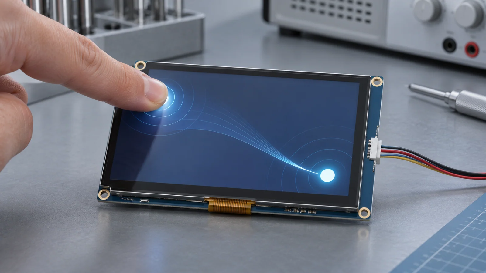
You rotate the interface for a portrait panel mounted sideways, or flip it 180 degrees because the product is mounted upside down. The picture looks right, but pressing the top-left button triggers the bottom-right one. A coordinate-frame mismatch is one possibility; verify the touch hardware and configuration as well.
This guide gives the arithmetic for each rotation, a four-corner test that identifies the error from the readings, and a list of the layers where the correction can live. Choosing the touch technology is covered in the PCAP vs resistive comparison, and the electrical side of a capacitive touch module is covered in the industrial PCAP design guide. The panel sizes and ranges below are assumptions chosen to make the numbers visible. They are not data for any module.
Two frames, and the layers that rotate
The touch controller reports a point as a pair of numbers in the sensor's frame: an origin in one corner, axes that run in fixed directions, and a range, for example 0 to 479 across and 0 to 799 down. The picture lives in the interface frame, which has its own origin and size. When the interface is rotated, the picture's frame changes and the sensor's does not.
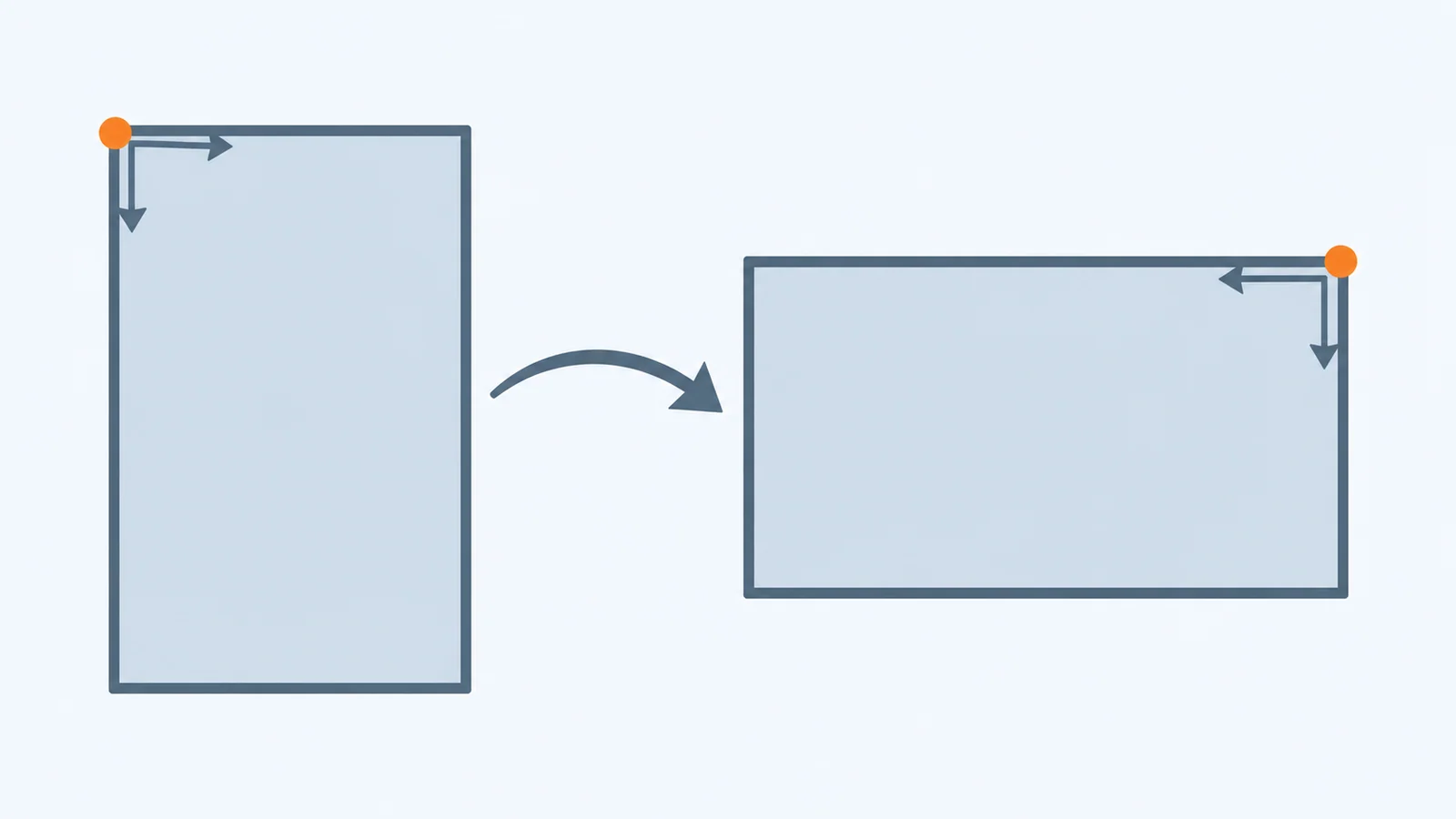
Rotation can happen at several layers, and each one turns the picture without touching the sensor data.
| Layer | What it turns | Effect on touch data |
|---|---|---|
| Panel scan direction (a driver IC setting) | The picture inside the panel | None. The sensor still reports its own frame |
| Display controller or framebuffer rotation | The picture as it is scanned out | None |
| Graphics library rotation | The rendered picture, in software | Depends on the library and its version; check it |
| Windowing or operating-system input stack | The desktop or compositor orientation | Depends on the system; often a configured transform |
| Touch controller or its driver configuration | Nothing in the picture | Can swap, invert and scale the reported points |
Which direction "rotate 90" turns the picture depends on the layer that does it. Do not assume it. Use the corner test below to find out which way your picture turned, and choose the mapping from that.
The mapping, with numbers
Take a native panel that is 480 pixels wide and 800 pixels tall, such as a portrait-native module, and rotate the interface to 800 by 480. Let the touch controller report (x, y) in the native frame, with W = 480 and H = 800. The table gives the interface point for each rotation of the picture, clockwise as the user sees it. Coordinates start at 0, so the largest value is size minus 1. The last column is a worked example for a touch reported at native point (100, 600).
| Picture rotation | Interface x | Interface y | Interface size | Example: native (100, 600) |
|---|---|---|---|---|
| 0° | x | y | 480 × 800 | (100, 600) |
| 90° clockwise | H − 1 − y | x | 800 × 480 | (199, 100) |
| 180° | W − 1 − x | H − 1 − y | 480 × 800 | (379, 199) |
| 270° clockwise | y | W − 1 − x | 800 × 480 | (600, 379) |
Two things stand out. At 90 and 270 degrees the axes swap, so the width and height trade roles. That is why a mapping that uses the width where the height is needed gives a small error on a nearly square panel and a large one on a long, narrow panel. At 180 degrees both axes invert but nothing swaps.
The same mapping in two configuration systems
Two common configuration systems express the same transform. The Linux device tree binding for touchscreens defines properties for an inverted X axis, an inverted Y axis, swapped X and Y axes, and a reported range, and states that swapping is done after inverting the axis. libinput describes a calibration matrix of six numbers, the first two rows of a matrix, with an example matrix for each rotation. The table lines the two up with the mapping above. The matrix examples have a translation term of 1, which implies coordinates scaled to the range 0 to 1, so confirm the scaling in the documentation for the version you use.
| Picture rotation | Device tree properties (inversion applies first, then swap) | libinput example matrix |
|---|---|---|
| 90° clockwise | touchscreen-inverted-y and touchscreen-swapped-x-y | 0 -1 1 1 0 0 |
| 180° | touchscreen-inverted-x and touchscreen-inverted-y | -1 0 1 0 -1 1 |
| 270° clockwise | touchscreen-inverted-x and touchscreen-swapped-x-y | 0 1 0 -1 0 1 |
As a check on the arithmetic, apply the 90-degree matrix to the example point scaled to the range 0 to 1, which is (100 / 479, 600 / 799). The result, scaled back to the 800 by 480 interface, is (199, 100), the same as the table above. The 180 and 270 degree examples also agree. This confirms that the formulas, the property combinations and the matrices describe one transform, as long as your picture turned the way the table assumes.
A four-corner test that names the error
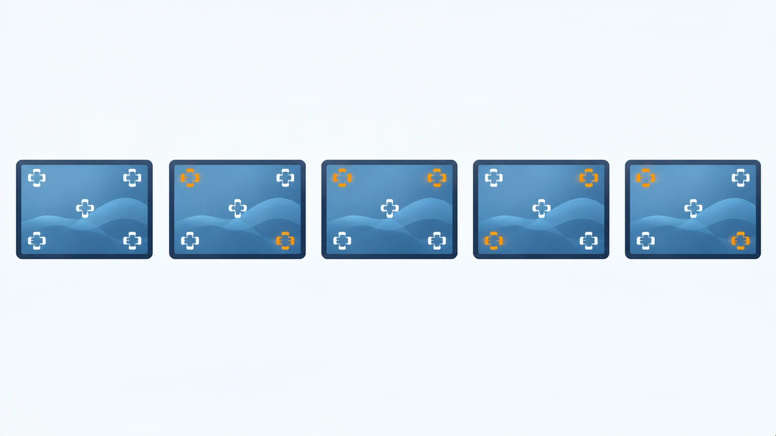
Do not guess from a single touch. Touch the four corners of the displayed picture and a point near the centre, and log the coordinates your software receives at the layer you are testing. The pattern identifies the error. The table assumes the final interface is 800 by 480, so the correct readings are (0, 0), (799, 0), (0, 479) and (799, 479).
| Touched corner | Correct | X inverted | Y inverted | Both inverted | X and Y swapped |
|---|---|---|---|---|---|
| Top left | (0, 0) | (799, 0) | (0, 479) | (799, 479) | (0, 0) |
| Top right | (799, 0) | (0, 0) | (799, 479) | (0, 479) | (0, 799) |
| Bottom left | (0, 479) | (799, 479) | (0, 0) | (799, 0) | (479, 0) |
| Bottom right | (799, 479) | (0, 479) | (799, 0) | (0, 0) | (479, 799) |
A swap on a rectangular panel is easy to spot: the top-right corner reads (0, 799), a y value that does not exist on a 480-pixel-tall interface. A swap combined with an inversion gives the 90 and 270 degree patterns, so read the swap first, then the inversions. The top-left corner staying at (0, 0) is not proof that all is well, because a swap leaves that corner unchanged, so always read all four.
Scale and offset errors look different
| What you see | Likely cause | Check |
|---|---|---|
| The marker is right near the origin and the error grows toward the far edge | Reported range does not match the interface size. For example, a controller reporting 0 to 4095 against an 800-wide interface puts the far edge about 5.1 times too far | The reported maximum against the interface size, and where the range is set |
| The same shift at every point | An origin or offset setting, or a front-panel opening that is not centred on the sensor | Offset settings, then the cover drawing |
| Correct in one axis, wrong in the other | The wrong dimension used for one axis, often after a swap | Which size feeds each axis in the mapping code |
| Right at the corners, wrong in the middle | Possible non-linear sensor or edge behavior, or a more complex mapping error | A linearity test; see the validation checklist in the PCAP design guide |
Correct it in one layer
Once the corner test names the error, decide which layer owns the fix, and apply it there only. A correction made in two places turns a clean mirror into a different mirror, and the symptom changes without going away.
| Layer | Good fit when | Watch for |
|---|---|---|
| Touch controller configuration | The mounting is fixed and the controller supports swap, invert and range settings | Settings can differ by configuration version; record it |
| Touch driver or device tree | A Linux-style stack with a fixed mounting | Properties describe a static mounting, not a rotation chosen at run time |
| Input stack or compositor matrix | The orientation can change while the system runs | Make sure the matrix is not applied on top of a driver-level swap |
| Graphics library | The library transforms pointer coordinates for you | Check what your version does before adding your own transform |
| Application code | No lower layer can do it | It must change with every rotation setting, so keep it in one function |
Graphics libraries need a version check
LVGL's documentation says that setting a rotation swaps the horizontal and vertical resolutions internally but does not perform the actual rotation, and it describes rotating the buffer in the flush callback when the panel cannot do it. That page does not say what happens to touch. A user thread on LVGL 9.2.2 quotes source code that transforms pointer coordinates after the read callback for 90, 180 and 270 degree rotation, and the same thread ends without agreement on whether the result is correct. The practical lesson is the same for any library: find out whether your version transforms pointer coordinates, test with the corner table, and make your own touch callback return coordinates in the frame the library expects.
One display vendor's article on its own 7-inch module makes a similar point from the hardware side. It states that rotation has to be handled in software and that its touch controller always reports raw, unmodified coordinates, so touch alignment must be implemented in software too. That is one vendor and one controller, so confirm how yours behaves.
Mapping versus calibration
A mapping is exact arithmetic: swap, invert and scale, with no tuning. Calibration measures a particular sensor and corrects its offset and gain. They solve different problems, and the corner test tells them apart. Whole corners trading places is a mapping error. A smooth error that grows toward one edge, or that is the same everywhere, points to range, offset or calibration.
Resistive touch with an analog controller commonly needs a calibration step. A capacitive sensor with its own controller usually reports points in the range the controller is configured for, so a PCAP problem may involve mapping, range, calibration or electrical issues; test the actual system. See the touch technology comparison for how the two differ. Calibration after assembly is a different question from mapping: the cover glass, bezel opening and bonding can all shift where a touch lands, so run the corner test on the finished stack, not only on the bare module.
An orientation record sheet
| Item | What to record | Your entry |
|---|---|---|
| Native panel size and orientation | Width, height and which edge is the top at 0 degrees | |
| Interface size and rotation | Size after rotation, and which way the picture turned | |
| Layer that rotates the picture | Panel register, display controller, library or system | |
| Touch controller frame | Origin corner, axis directions and reported range, with the source document | |
| Layer that corrects touch | The one layer that owns the transform, and its setting | |
| Corner readings | Top left, top right, bottom left, bottom right and centre as received | |
| Scale and offset | Reading at the far edges and any constant shift | |
| Versions | Touch firmware and configuration, driver, library and application | |
| Stack tested | Bare module or finished stack with cover, and its drawing revision |
Keep the sheet with the software baseline. Who owns the driver, the library port and the configuration is covered in the software integration checklist. Portrait-native panels are where this problem usually starts: see the bar-type selection guide for how orientation shapes the interface design. Published touch configurations are on the PCAP modules page.
Questions to ask the supplier
- Does this model have a touch panel, and which controller does it use?
- What are the controller's origin corner and axis directions relative to the display's native orientation, as drawn on the approved drawing?
- What range does the controller report, and can the range, swap and inversion be set in its configuration?
- Which configuration or firmware version applies to this module revision, and how are changes announced?
- For a bonded assembly, are the display and touch orientations shown on the same drawing?
- Is there a reference mapping for the host and software you use, and for which revision?
Send the answers with your host, software stack, native panel orientation, the rotation you need and the four-corner readings through a project review, so the mapping is checked against a real configuration.
Touch coordinates after rotation FAQ
Why are touch coordinates wrong after I rotate the screen?
The touch controller keeps reporting points in the sensor's own frame, with its own origin, axis directions and range, while the picture has been turned into a different frame. Unless the touch data is transformed to match, a touch lands mirrored, swapped or offset. The transformation has to be applied in exactly one layer.
Do I need calibration, or only swapped and inverted axes?
Run the four-corner test. A swap or inversion shows up as an exact corner pattern: whole corners trade places. A calibration or range problem shows up as an error that grows smoothly toward one edge or stays constant everywhere. Fix the exact mapping first, then look at scale and offset.
Does LVGL rotate touch coordinates automatically?
It depends on the library version and on how the display and input device are set up. LVGL's rotation documentation describes the display side and does not mention touch, and a user thread quotes library source that transforms pointer coordinates for 90, 180 and 270 degree rotation. Read the source of the version you use, test it, and make sure the transform is not applied both in your touch callback and in the library.
Why does touch work at 0 and 180 degrees but not at 90 and 270?
Those two rotations swap the axes, and the others do not. A fault that appears only at 90 and 270 may involve the swap: it is missing, applied twice, or the inversion uses the width where the height is needed. The error is easy to miss on a square panel and obvious on a rectangular one.
Technical references
- Linux kernel — touchscreen device tree binding (touchscreen.yaml): the size, inverted-x, inverted-y and swapped-x-y properties, and the order in which they apply. This link points to a mirror of the kernel source tree.
- libinput — Static device configuration via udev: the calibration matrix property and its example matrices for 90, 180 and 270 degree rotation.
- LVGL — Display rotation: lv_display_set_rotation, software rotation in the flush callback, and the render-mode limits. Read the version you use.
- LVGL forum — Inconsistency between display rotation and touchscreen coordinate rotation: a user report on LVGL 9.2.2 that quotes source code for pointer transforms. A user thread, not documentation, and it does not settle the question it raises.
- Riverdi — Screen rotation on a 7-inch STM32 display: one display vendor's example of touch axis swapping and inversion per rotation. It describes that vendor's own touch controller.
Related engineering guide
For a separate integration check, read TFT LCD Backlight On but No Image.
Send Us Your Orientation and Touch Details
Share the native panel size and orientation, the rotation you need, the touch controller's reported range and axis directions, and the four-corner readings. TFTWorks can review the published display information against that configuration.
Request a Project Review Read the PCAP design guide
Send supporting files with the same project reference
The web form does not upload attachments. Email your configuration records and drawings, or send them through WhatsApp.
Publisher and scope. Published by TFTWorks, operated by Guangdong Dexing Microelectronics Co., Ltd. The coordinate examples use assumed panel sizes and touch ranges, and the mapping formulas are plain arithmetic checked against the referenced examples. They make no claim about any touch controller, driver or library. Whether a module has a touch panel, and which controller it uses, is model-specific: confirm it against the current model-specific datasheet. This guide does not assume that any operating-system driver, library port or board support package is supplied with a module.