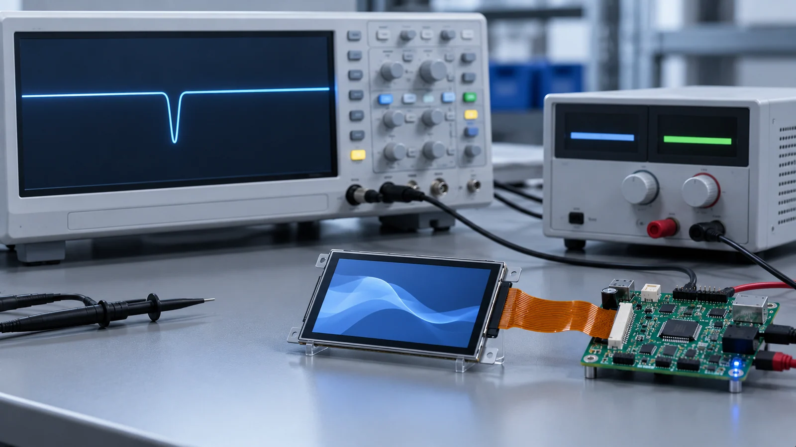
Many products reset or fail to start only when the display is connected, only with a battery in a certain state, or only the first time after a cold start. The average current of the display tells you little about this, because the problem lasts for microseconds to milliseconds. This guide is about that startup transient. Average power and runtime belong to the TFT LCD power budget guide, and the static power, reset and backlight checks for a display that does not light up are in the interface troubleshooting guide.
The calculations below use assumed values so the arithmetic is visible. They are not measurements of any module, and no module's startup current is stated or implied.
Where the startup surge comes from
Several things can draw current at the same moment. The table separates them so each can be tested on its own.
| Source | What happens | How to test it |
|---|---|---|
| Capacitors on the display supply | Decoupling and bulk capacitors, and the module's own input capacitance, charge when power arrives. The current follows the slope of the voltage ramp | Capture the supply current and rail during the first milliseconds, with the backlight off |
| Backlight driver starting | A step-up converter's output follows its input through the inductor and diode before switching begins, and a surge can occur when it starts to switch, especially from batteries or current-limited sources | Enable the backlight separately from the logic supply and compare |
| Module internal supplies and logic | The module's own start-up, as defined by its datasheet and power sequence | Follow the model-specific power-up sequence and note where the current rises |
| Switching a load onto a live rail | Closing a switch or plugging a connector adds a discharged capacitor to a rail that is already up | Check whether the display rail is switched, and how fast |
| The host and other loads starting together | Processor, memory, radios and motors can all draw their start-up current in the same interval | Delay or stagger the other loads and watch whether the dip changes |
| Backlight commanded to a high level at power-on | If the backlight starts at a high level, its first current draw is at that level, not at a gentle one | Start with the dimming input low and ramp it up |
Two manufacturer notes give the general mechanisms. Texas Instruments' application note on inrush current states that the charging current into a capacitor is set by the slope of the voltage ramp, I = C × dV/dt, so a faster ramp or more capacitance means more current, and that a surge can also occur when a capacitive load is switched onto a live rail. Analog Devices' design note on a switching regulator describes inrush as especially troublesome when a regulator runs from batteries or a current-limited source, and shows a boost converter that, without soft-start, can draw a large surge at the point where it begins to switch even though its output has already followed the input through the inductor and diode.
Why the rail dips: a worked example
A dip needs two things: a surge and impedance between the source and the display. The impedance is the battery's internal resistance, any cable, the connector contacts and the board traces. Toshiba's introduction to load switch ICs makes the same point for the input side: inrush current flowing through the trace impedance can pull the input voltage down. If the regulator cannot supply the surge at all, TI's note says the rail can collapse completely and other modules on it may reset into an undesired state.
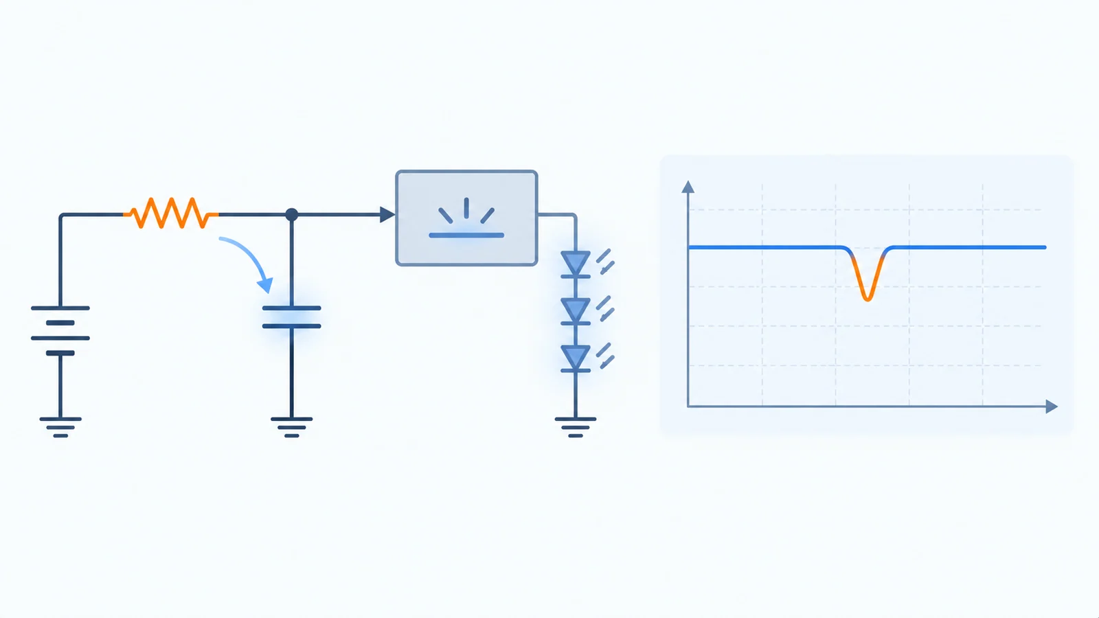
Take a display rail with an assumed total of 100 µF of capacitance, a 3.3 V supply, and an assumed 0.3 Ω of source resistance made up of battery, cable and connector. If the rail rises in a straight line over a time t, the average charging current is C × V / t. The table shows how strongly the ramp time matters. It models only the capacitor charging, and it ignores the regulator's current limit, which in a real design would cap or collapse the surge.
| Rise time | Charging current, C × V / t | Dip across 0.3 Ω | Rail at the load from 3.3 V | Against an assumed 2.7 V threshold |
|---|---|---|---|---|
| 100 µs | 3.3 A | 0.99 V | About 2.31 V | Below the threshold |
| 1 ms | 0.33 A | 0.099 V | About 3.20 V | Above |
| 10 ms | 0.033 A | 0.0099 V | About 3.29 V | Above |
For a capacitive load, changing the voltage ramp can change charging current. The outcome also depends on source response, load behavior and reset thresholds; investigate each before choosing a remedy. It also shows why a bench power supply can hide the problem: its source resistance is often lower than that of a battery, a long cable and a connector, so the same startup looks fine on the bench and fails in the product.
Diagnose in stages
| Step | Do this | What it tells you |
|---|---|---|
| 1. Read the reset reason | Log the host's reset cause at the next boot. Some hosts report it; for example, Espressif's ESP-IDF defines a brownout reset reason and a function that returns the cause of the last reset | Whether the event is a brownout or reset-circuit trip, a watchdog, or something else |
| 2. Capture at the load | Probe the rail at the display connector or the display regulator output, DC-coupled, with a short ground connection. Trigger on a falling edge or on the enable signal | The real minimum voltage the display and host see, not the voltage at the source |
| 3. Add the control signals | Capture logic enable, backlight enable, reset and the host rail on the same time base | Which event lines up with the dip |
| 4. Stage the events | Boot the host with the display supply off or the backlight disabled, then enable the logic supply, then the backlight. Disconnect or hot-plug a module only if the design and the module allow it | Which step creates the surge |
| 5. Change the backlight start | Hold the backlight control at its lowest level at power-on, then ramp it after the rails are stable | How much of the dip is the backlight driver |
| 6. Change the source | Repeat with a current-limited bench supply, the real battery, the final adapter and a shorter or longer cable | How much of the dip is source impedance |
| 7. Compare with the thresholds | Put the minimum voltage against the host's brownout level, any supervisor threshold and any regulator under-voltage lockout, taken from their datasheets | The real margin, and which device trips first |
| 8. Repeat at the extremes | Test at the lowest battery state and the temperature extremes you support, and on the first cold start | Whether the margin holds when source impedance is at its worst |
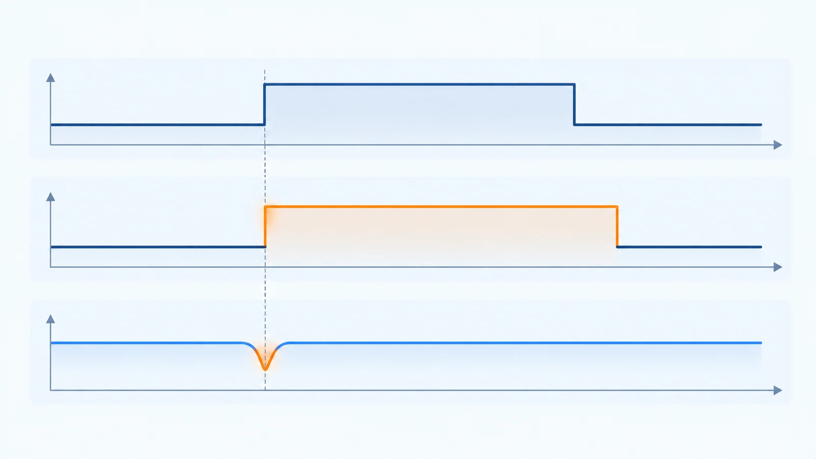
A multimeter will not show any of this. It averages the reading and misses a peak that lasts a few milliseconds or less. Use an oscilloscope, and either a current probe or a small series sense resistor on the display supply, and look at the voltage at the load while you do.
Shape the surge before enlarging the supply
| Technique | What it does | Check |
|---|---|---|
| Sequence the supplies | Brings up the logic supply, then the host's display setup, then the backlight, instead of everything at once | The module's power-up sequence in its datasheet, including any required order and delays |
| Slew-rate-controlled switch on the display supply | Limits the rate of voltage rise, and with it the charging current. Texas Instruments and Toshiba both describe this, and Toshiba notes that inrush limiting is also called slew rate control or soft start | That the slower rise still satisfies the module's power-up timing |
| Backlight driver soft-start | Ramps the converter's current limit at start-up. A step-up converter datasheet from Texas Instruments describes its adjustable soft-start as preventing high inrush current during start-up | Whether your backlight driver, on the module or on your board, has this feature, and its default setting |
| Ramp the dimming level | Starts the backlight at a low level and raises it after the rails settle | The dimming input's state before the host drives it; see the dimming guide |
| Stagger other loads | Delays radios, motors and heaters until the display has started | That the delays do not break the product's start-up time requirement |
| Lower the source impedance | Shorter or heavier power path, connector rated for the peak, a source that can supply the surge. TI notes that peak inrush can exceed the ratings of connectors and traces | Connector and trace ratings against the measured peak, not only the average |
| Choose the brownout level deliberately | Keeps the reset threshold consistent with what the system can tolerate | That lowering a threshold does not just hide a dip that still disturbs other devices on the rail |
A startup event record sheet
Startup problems tend to return when a supply, a cable or the firmware changes. Record the setup and the result so a later build can be compared. The sheet below is a blank template with no values filled in.
| Item | What to record | Your entry |
|---|---|---|
| Source | Battery, adapter or bench supply, its state and its current limit | |
| Power path | Cable length and gauge, connector type and any switch or fuse | |
| Display rails | Logic and backlight supplies, voltages, switching and enables | |
| Sequence used | Order and delays between the rails, host setup and backlight | |
| Backlight start state | Dimming input level at power-on and the ramp, if any | |
| Capture setup | Probe point, trigger, and the signals shown together | |
| Minimum voltage at the load | The lowest value seen, and the time it occurred | |
| Thresholds | Host brownout level, supervisor and regulator lockout, from their datasheets | |
| Reset reason | What the host reports after the event | |
| Change made and result | The mitigation applied, and the firmware and hardware revision tested |
Keep the sheet with the power budget and the software baseline. The mode-by-mode averages go in the power budget guide, and who owns the initialization and sequencing code is covered in the software integration checklist. For battery-powered equipment, see the handheld devices application page.
Questions to ask the supplier
- What is the required power-up sequence and the allowed rise time for each supply of this module?
- Is the backlight driver on the module or on the host board, and does it have a soft-start?
- What state is the backlight in at power-on if the dimming input is not yet driven?
- Is there startup or peak current data for the logic and backlight supplies, and under which conditions was it taken?
- Does the module or its connector support hot-plug, or must it be connected with the power off?
- Is there a reference power-up and initialization sequence for the module revision you will use?
Send these answers with your supply type, rail voltages, the observed dip and the model you are using through a project review, so the startup plan is checked against a real configuration.
Startup current and brownout FAQ
Why does my system reset when the TFT LCD turns on?
At power-on the display side can briefly draw much more current than it does in normal operation, mainly to charge capacitors and to start the backlight driver. If the source and wiring cannot supply that surge, the shared rail dips, and a reset circuit or brownout detector on the host may trip. Confirm it by reading the host's reset reason and capturing the rail at the load during the event.
How do I measure the startup current of a display?
A multimeter averages the reading and misses a short peak. Use an oscilloscope with a current probe or a small series sense resistor on the display supply, and also watch the rail voltage at the load. Trigger on the enable signal or on a falling edge so the capture includes the first moments after power is applied.
Is the backlight the cause of the startup dip?
It is often a large contributor, because the backlight driver starts a switching converter and its output capacitor must be charged, but it is not always the only one. Find out by staging the events: start the host with the backlight disabled, then enable the logic supply, then the backlight, and see which step produces the dip.
Can I fix a startup dip just by adding capacitors?
Not reliably. More capacitance near the load can reduce the dip the load sees, but the extra capacitance must itself be charged, which raises the surge the source has to supply. Slowing the rise with sequencing, a slew-rate-controlled switch or a soft-start usually works on the cause.
Technical references
- Texas Instruments — Managing Inrush Current (SLVA670): capacitor charging current, I = C × dV/dt, slew-rate control in load switches and the effect on the input rail.
- Toshiba — Basics of Load Switch ICs, inrush current: inrush into the output capacitor, voltage drop across input trace impedance, and slew rate control, also called soft start.
- Analog Devices — Design Note 365, ThinSOT Switching Regulator Controls Inrush Current: inrush from batteries or current-limited sources, and soft-start in a boost converter.
- Texas Instruments — TPS61087 step-up converter datasheet, soft-start: an adjustable soft-start that prevents high inrush current during start-up, as an example of a boost converter used in TFT LCD and LED applications.
- Espressif — ESP-IDF system API, reset reason: an example of a host that reports a brownout reset reason.
Related engineering guide
For a separate system-level concern, read TFT LCD Screen Tearing: Framebuffer, VSYNC and TE Signal Troubleshooting.
Send Us Your Power-Up Details
Share the supply type and rail voltages, the cable and connector, the observed dip, the host's reset reason and the candidate module. TFTWorks can review the published display information against that configuration.
Request a Project Review Read the power budget guide
Send supporting files with the same project reference
The web form does not upload attachments. Email your configuration records and drawings, or send them through WhatsApp.
Publisher and scope. Published by TFTWorks, operated by Guangdong Dexing Microelectronics Co., Ltd. The tables use assumed values and make no claim about the startup current, power sequence or backlight driver of any module. The referenced notes describe specific load switches, converters and one host family, so confirm every value against the current model-specific datasheet and your own measurements. This guide does not assume that any initialization code or sequencing firmware is supplied with a module.