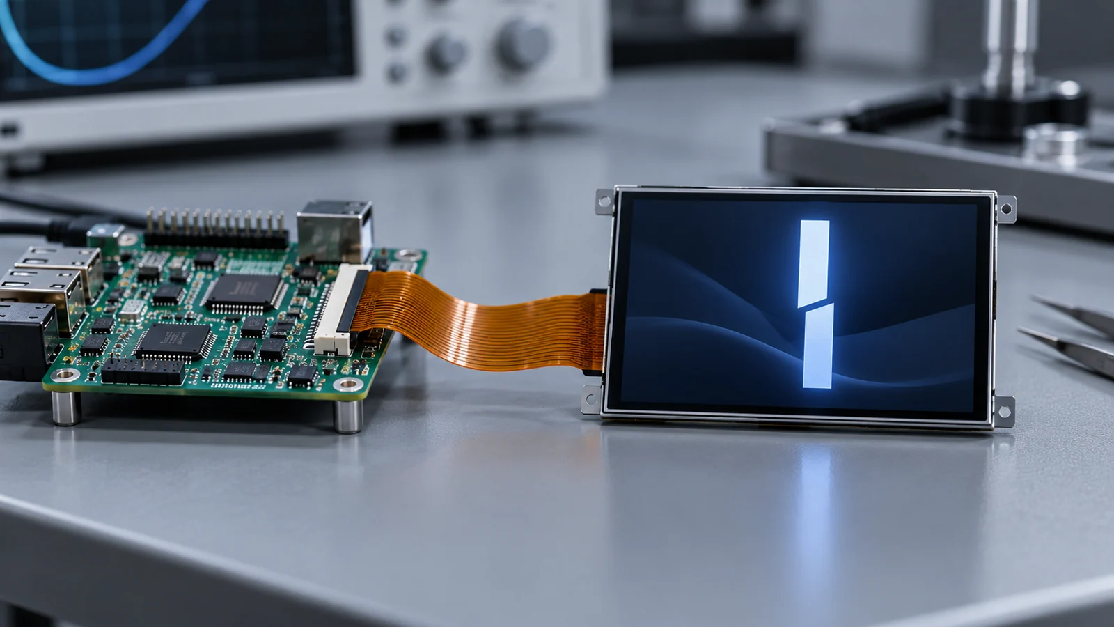
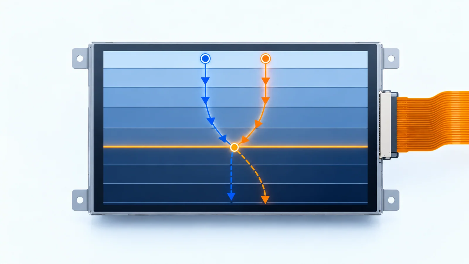
Screen tearing looks like a horizontal break in a moving image: the top part of the screen shows one frame and the bottom part shows another. It is most visible on fast horizontal motion, scrolling lists and animated gauges, and it often shows up only after a product moves to a richer user interface or a larger display.
This guide is about the synchronization between the thing that writes pixels and the thing that reads them. How much RAM the framebuffer needs is a separate question, covered in the framebuffer memory calculation guide. The examples here use assumed timing so you can see the arithmetic; replace them with the values from your module's datasheet.
Decide who owns the scan
Every display is refreshed from some memory, and the question is whose. The answer decides which tool applies.
| Architecture | Who reads the image memory | Where a tear comes from | Synchronization tool |
|---|---|---|---|
| Host-scanned: parallel RGB, LVDS from a host or bridge, MIPI DSI video mode | The host's display controller, continuously, line after line, from a framebuffer | The framebuffer being drawn into or swapped while the controller is reading it | Two buffers, swapped at the VSYNC or vertical-blanking point |
| Panel with its own display memory: many SPI, MCU-bus and MIPI DSI command-mode modules | The panel's driver IC, from its internal memory, at its own refresh rate | The host's write crossing the point the panel is reading | The panel's TE output, used to time the start of each write |
| A bridge or controller board with its own frame memory | Possibly both sides, one after the other | Either hop, so the two must be checked separately | Ask which side owns synchronization and whether it adds a frame of delay |
The interface families themselves are described in the interface guide. If you are unsure which architecture your module uses, the model-specific datasheet and pin table are the place to look, not the connector shape.
The timing arithmetic behind a tear line
Two short calculations show why tearing is a timing problem. Both use assumed values, not measurements of any module.
Host-scanned: how long is the safe window?
Take an 800 × 480 panel with an assumed total of 1,056 × 525 pixels including blanking, refreshed at 60 Hz. The frame period is 1 / 60 s, about 16.67 ms. Divided over 525 total lines, one line takes about 31.7 µs. The 480 active lines take about 15.24 ms, and the 45 remaining lines of vertical blanking last about 1.43 ms.
That 1.43 ms is the assumed vertical blanking interval. Actual memory fetch and prefetch behavior depends on the controller; a supported vertical-blanking reload can provide a safe buffer change. A swap requested at a random time lands somewhere in the 15.24 ms of active scanning, and the part of the screen already drawn comes from the old buffer.
Panel with its own memory: can the host write fast enough?
Take a 320 × 240 panel stored as RGB565, which is 153,600 bytes or 1,228,800 bits per frame. Over a single-data-line SPI bus at an assumed 40 MHz, one bit per clock and ignoring command and gap overhead, a full frame takes 1,228,800 / 40,000,000 = 30.72 ms. That is about 1.8 times the 16.67 ms period of a panel assumed to refresh at 60 Hz. At double the clock the transfer still takes 15.36 ms, barely under one period with no allowance for overhead.
A full-frame write cannot finish inside one panel refresh at that bus speed, so the write may overlap the panel's read and produce tearing; the outcome also depends on scan direction, phase and the controller. Sending less data helps: a 100 × 50 region at 2 bytes per pixel is 10,000 bytes or 80,000 bits, about 2.0 ms at the same assumed clock. But a smaller write can still tear if it starts at a random moment, which is why the start of each write needs a timing reference.
| Case | Assumed inputs | Result | What it means |
|---|---|---|---|
| Frame period | 60 Hz | About 16.67 ms | The time budget for one refresh |
| Line time | 525 total lines at 60 Hz | About 31.7 µs | Scan speed down the screen |
| Vertical blanking | 45 lines of 525 | About 1.43 ms | The window to change buffers |
| Full-frame SPI write | 320 × 240 RGB565, 40 MHz, one bit per clock | 30.72 ms | Longer than one refresh period |
| Partial SPI write | 100 × 50 RGB565, 40 MHz | About 2.0 ms | Shorter, but still needs a start reference |
Host-scanned interfaces: swap during vertical blanking
With a host-scanned interface the display controller keeps reading the framebuffer whether or not your code has finished drawing. ST's application note on its LTDC display controller puts the single-buffer risk plainly: when only one framebuffer is used, the framebuffer computation can be displayed on the screen. It lists double buffering as the common remedy, and notes that even then a tearing effect may appear when the controller and the framebuffer update are not synchronized. Its suggested fix is to use the VSYNC signal to coordinate the two.
Two buffers, one rule
The model is simple. The controller reads the front buffer while the CPU or a graphics engine draws into the back buffer. When a frame is finished, the two swap roles, and the swap takes effect at the end of the displayed frame. ST's note describes two ways to do it on that controller: a line interrupt on the last screen line whose handler flips the buffers, or a shadow-register reload set to take effect during vertical blanking, which changes the framebuffer address on the VSYNC period. Other hosts offer equivalents under other names. Espressif's documentation for the ESP32-S3 RGB driver takes the same approach in a different form: it calls two screen-sized frame buffers the easiest way to avoid tearing, keeps the buffer the CPU writes and the buffer the DMA reads different, and provides a VSYNC event callback.
The common thread is that the host never edits the buffer being scanned out and never changes which buffer is scanned except at the frame boundary.
Common ways to defeat the scheme
- Copying instead of swapping. If the finished image is copied into the displayed buffer while the controller reads it, the copy can tear exactly as drawing directly would.
- Swapping at an arbitrary time. A swap that is not tied to the frame boundary lands in the middle of the 15.24 ms scan from the example above.
- Rendering that finishes late. If drawing misses the blanking window, the old frame stays for another refresh period. That shows up as a lower frame rate or judder, not a tear, and it is a sign the render time is the real limit.
- A render mode that writes into the live buffer. Graphics libraries differ here. LVGL's documentation, for example, describes partial mode with buffers smaller than the display, direct mode, and full mode with two display-sized buffers working like traditional double buffering. Whether a partial or direct update ends up writing into a buffer that is being scanned depends on how your display driver connects the library to the controller, so check this against the library version you use.
- Bandwidth starvation mistaken for tearing. If the memory cannot feed the controller fast enough, the picture can flicker or shift, and ST's note says the controller's FIFO underrun flag may be set. That is a bandwidth budget problem, covered in the framebuffer guide, and it should be ruled out first.
Panels with display memory: use the TE line with care
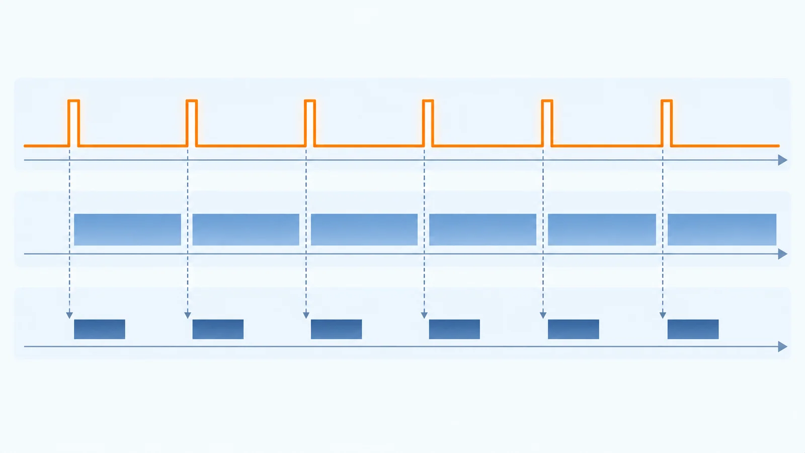
A panel that refreshes itself from internal memory is not fed by a continuous pixel stream from the host, so the host has no scan position to follow. Many of these driver ICs offer a separate tearing-effect output instead. In the ILI9341 datasheet, for example, the TE pin is described as the tearing-effect output used to synchronize the host to frame writing, activated by a software command. The commands that switch it on and off are named Tearing Effect Line ON and OFF, and the datasheet has separate sections on its modes and its timing.
What TE gives you, and what it does not
The MIPI DCS command that enables TE takes a parameter that selects whether the output marks vertical blanking only or both vertical and horizontal blanking; the vertical-only setting normally gives one event per refresh. A display vendor's application article suggests starting there, and treats a scanline-select command as an optional later step on controllers that support it. The same article offers several cautions that are worth keeping:
- TE is a marker, not a window. The useful point may be a rising edge, a falling edge or a chosen scanline. Read the driver IC's TE timing diagram, and measure the waveform on the board.
- TE does not add bandwidth. It does not speed up the link, lock the framebuffer, clean caches or prevent overlapping transfers. Firmware still has to do those things.
- The write must finish in time. The arithmetic in the timing section applies: if the whole write cannot finish within the panel's timing limit, TE helps you start on time but the write can still cross the read.
- TE settings can be lost. The article notes that reset, sleep, display-off or power loss may clear them, so they may need to be re-sent on resume.
- Do not wait forever. Use a timeout based on the slowest valid TE period, with a recovery path.
- Check the electrical level. The article warns that a 2.8 V TE output can damage a 1.8 V-only input. Compare the module's TE output level with the host pin's input limits before connecting it.
This is a vendor article rather than a standard, and the specifics vary by driver IC, so treat it as a source of questions to check in your own datasheet, not as settings to copy.
| Item | Check | Record |
|---|---|---|
| Is TE available on this model? | Pin table and datasheet; the connector shape alone does not say | |
| Output level and type | Voltage and output type against the host pin's input limits | |
| Enable command and mode | Vertical-only or vertical plus horizontal, as the datasheet defines them | |
| Which edge starts the frame | The datasheet's TE timing diagram, confirmed on a scope | |
| Measured TE period | One event per refresh in vertical-only mode | |
| Write time against the refresh period | Your frame or region size, bus clock and overhead | |
| Re-enable after reset or sleep | Whether the settings survive, and where firmware re-sends them | |
| Timeout and recovery | What happens if no TE event arrives |
From symptom to first check
| What you see | Likely area | Check first |
|---|---|---|
| A horizontal break that moves up or down from frame to frame | Write or swap not tied to the frame boundary | Host-scanned: where the swap happens. Panel with memory: whether TE is enabled and used |
| A break at nearly the same screen position every frame | A fixed offset between the trigger and the write, or a write slower than the panel read | The edge used for TE, the delay before the write starts, and the transfer time |
| Tearing only during heavy animation or scrolling | Rendering or DMA finishing late, or contention for memory | Render time against the refresh period, and other bus traffic |
| Tearing only in partial updates | Regions written at an arbitrary moment | Whether each region write is started from the sync marker |
| The image shifts, flickers or shows garbage rather than a clean break | Underrun or a bandwidth shortfall, not tearing | The bandwidth budget and the controller's underrun flag |
| Horizontal bands visible only on camera | Backlight dimming against camera exposure | Look at the screen by eye, and see the camera banding section of the dimming guide |
When you test, use a high-contrast pattern that moves horizontally, such as a vertical bar crossing the screen, at the highest content load you expect. A static test image will not show tearing. If you need to capture evidence, remember that a camera can add banding of its own.
A sync record sheet
Tearing fixes are easy to lose when the software changes. Record the synchronization setup the same way you would record a power sequence, and keep it with the build. The sheet below is a blank template with no values filled in.
| Item | What to record | Your entry |
|---|---|---|
| Display architecture | Host-scanned, panel with its own memory, or bridged | |
| Host peripheral and mode | Display controller or bus, and the mode it runs in | |
| Buffers | Count, size and memory location | |
| Change or write trigger | Which event starts a swap or a write (VSYNC, line interrupt, TE) | |
| TE connection | Used or not, pin, level, mode and edge | |
| Refresh rate and transfer time | Panel refresh period and measured write time | |
| Graphics library setting | Library, version and render mode | |
| Test pattern and load | Pattern, content load and observation method | |
| Result and build | Observed result, with the firmware version tested |
Questions to ask the supplier
- Does the module keep its own display memory, or is it scanned directly by the host?
- Is a TE output available on this model, on which pin, at what voltage and output type?
- Which TE modes does the driver IC support, and which edge marks the start of the frame?
- What is the panel's internal refresh rate, and how does it relate to the pixel clock or the input timing?
- If a bridge or controller board is used, does it hold a frame, and does it add delay or its own tearing risk?
- Is there a reference initialization sequence that enables TE, and for which module revision?
Send the answers with your host part number, interface, frame size, refresh requirement and the graphics library you use through a project review, so the synchronization plan is checked against a real configuration. To compare modules by interface first, see the industrial TFT modules by interface.
Screen tearing FAQ
What causes screen tearing on a TFT LCD?
Tearing appears when the image the display reads changes partway through a frame, so the top and bottom of the screen come from different frames. On a host-scanned interface this happens when the framebuffer is changed or swapped while the display controller is reading it. On a panel with its own display memory it happens when the host writes into that memory at a point the panel's own refresh read is crossing.
Does every TFT LCD module have a TE signal?
No. A TE output is a feature of some display driver ICs that hold their own display memory and take commands from the host, such as many SPI, MCU-bus and MIPI DSI command-mode panels. A module scanned directly by the host over parallel RGB, LVDS or MIPI DSI video mode has no need for it. Whether a given model exposes TE, on which pin and at what voltage, must be confirmed in its datasheet and pin table.
Does double buffering remove tearing?
Not by itself. Two buffers let the host draw out of sight, but the display must also change to the new buffer at a safe moment, normally during vertical blanking. Copying the new image into the buffer being displayed, or swapping at an arbitrary time, can still tear.
Will a faster SPI clock fix tearing?
A faster transfer can improve timing margin, but the outcome depends on scan direction, phase, update region and controller behavior. TE synchronization may help when supported; verify timing for the exact module and host. A faster SPI clock does not itself synchronize a host-scanned framebuffer swap. Work out the transfer time for your frame size before changing the clock.
Technical references
- STMicroelectronics — AN4861, LTDC synchronization with DMA2D and CPU: single and double buffering, VSYNC coordination, line interrupt and vertical-blanking reload, and blanking-period updates.
- STMicroelectronics — AN4861, creating a graphical application with LTDC: pixel clock, bandwidth requirements and the FIFO underrun flag.
- Espressif — RGB Interfaced LCD, ESP-IDF v5.3 for ESP32-S3: double frame buffer, bounce buffers and the VSYNC event callback, as one host's approach.
- LVGL — Setting Up Your Display(s): render modes, single, double and triple buffers, flush callback and flush-wait callback. Read the version you use.
- ILI9341 datasheet: the TE pin description, and the Tearing Effect Line commands, modes and timing sections, as an example of a panel driver with display memory.
- DisplayModule — How to use the MIPI DSI TE signal to prevent screen tearing: a display vendor's application article on TE modes and firmware cautions.
Related engineering guide
For a separate system-level concern, read TFT LCD Power-On Voltage Drop: How to Diagnose Startup Current and Brownout.
Send Us Your Host and Display Details
Share the host part number, the display interface, the frame size and refresh requirement, the graphics library and what you see on the screen. TFTWorks can review the published display information against that configuration.
Request a Project Review Read the interface troubleshooting guide
Send supporting files with the same project reference
The web form does not upload attachments. Email your configuration records and drawings, or send them through WhatsApp.
Publisher and scope. Published by TFTWorks, operated by Guangdong Dexing Microelectronics Co., Ltd. The timing examples use assumed values and make no claim about the performance of any host, driver or module. The referenced notes describe specific processors, one graphics library, one panel driver and one vendor's view of TE, so confirm every setting against your own host documentation and the current model-specific datasheet. Whether a given module provides a TE output is model-specific, and this guide does not assume that any operating-system driver or board support package is supplied with a module.