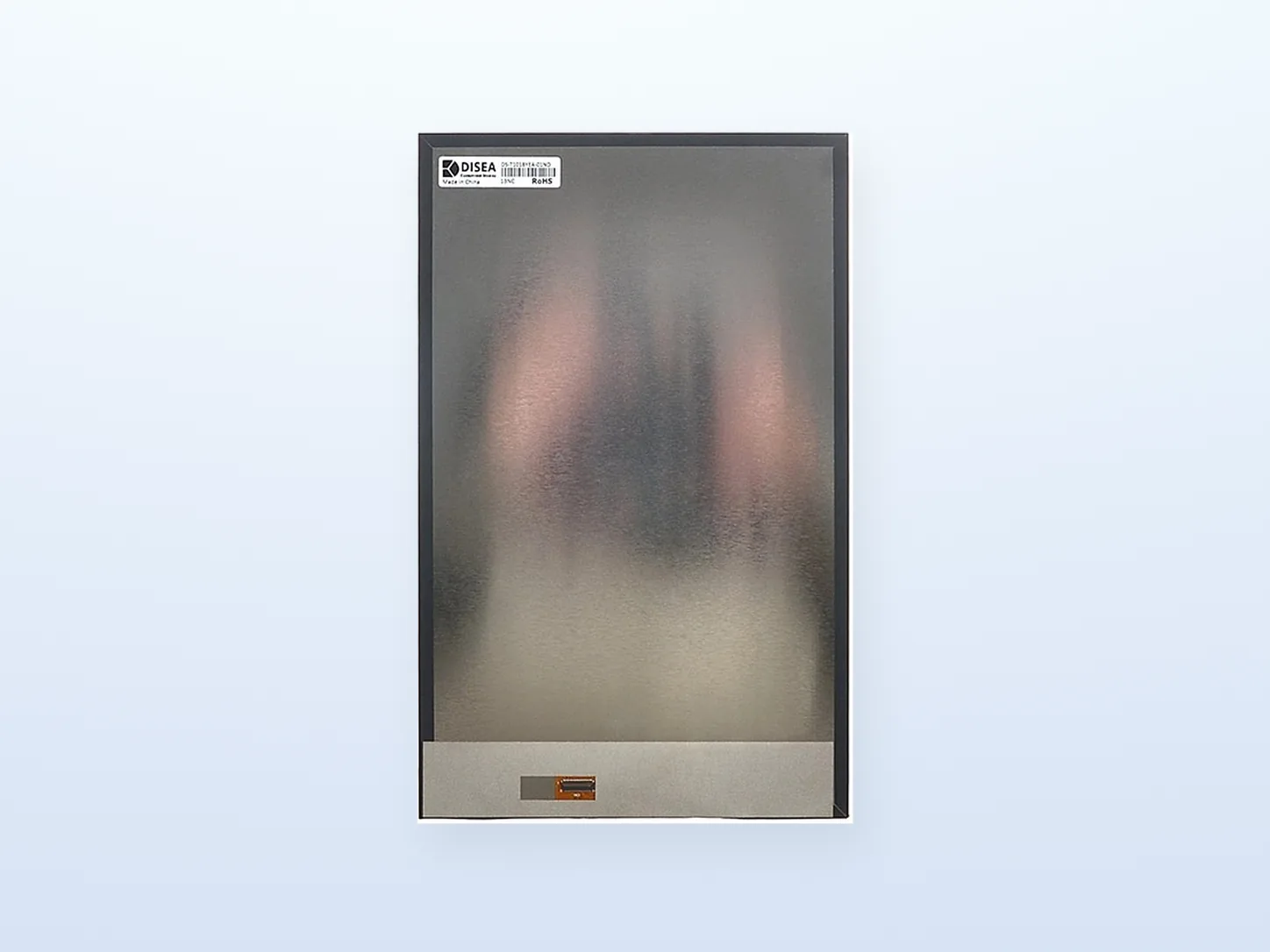
Rear structure reference
Use the approved drawing and pin table to confirm the connector, contact direction and local clearances. The image does not establish a pinout.
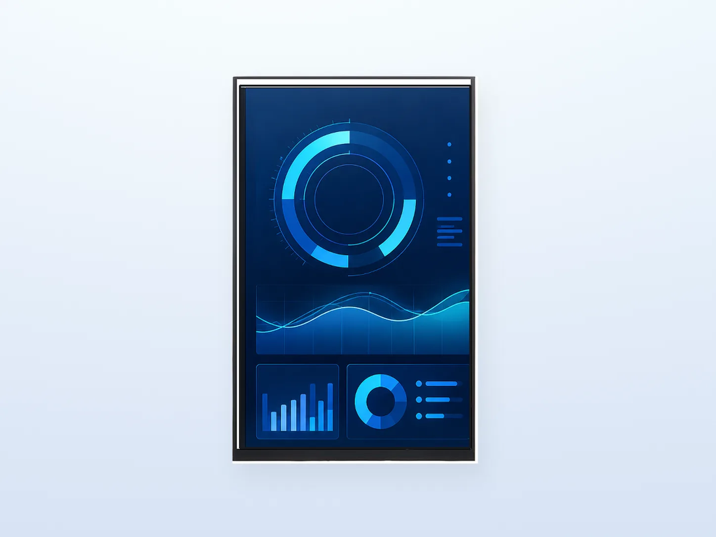
Supplied product presentation visual. Screen graphics are illustrative; this listing is for a bare LCD module, not a complete HMI or supplied software.
DS-T101BYEA-01ND is a 10.1-inch IPS TFT LCD with a native 800×1280 portrait format, 300 cd/m² luminance and a 4-lane, 31-pin MIPI interface. The catalog lists the JD9365DA-H3 LCD driver and no integrated touch panel.
Confirm the exact host, panel initialization, timing, connector mapping and power/reset sequence before design-in. A MIPI interface name alone does not establish compatibility.
Evaluate the 135.36×216.58 mm active area for a vertically organized equipment UI. Review the native pixel orientation, content layout, viewing distance and enclosure opening together.
This 800×1280 portrait module is a different electrical and mechanical option from the 1280×800 landscape LVDS and bonded-PCAP configurations. Reversing the resolution numbers or rotating software does not make the modules interchangeable.
The published configuration is an LCD component with no integrated touch panel. Any touch, cover lens, bridge board or complete enclosure requirement needs a separate configuration review.
Review the MIPI host and lane checklist →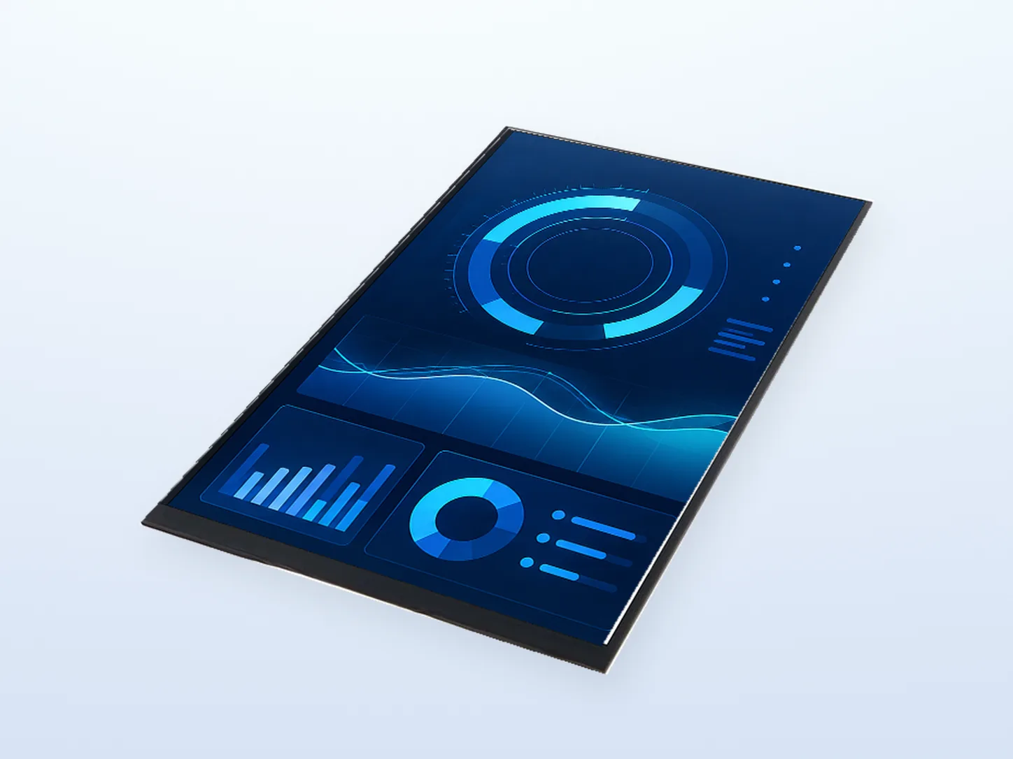
Review the original controlled drawing for the real mounting, connection and clearance requirements; the presentation image is not dimensional evidence.
Source: DISEA DS-series standard module list, 2026 V2.1, page 4, row 189. The table below is a summary, not an approved model-specific electrical datasheet.
| Item | DS-T101BYEA-01ND |
|---|---|
| Model | DS-T101BYEA-01ND |
| Diagonal size | 10.1 inch |
| Native resolution | 800×1280 (portrait) |
| LCD type | IPS TFT |
| Luminance | 300 cd/m² (300 nits) |
| Module interface | 4-lane MIPI, 31-pin |
| LCD driver IC | JD9365DA-H3 |
| Touch panel | No TP (no integrated touch panel) |
| Active area (W×H) | 135.36×216.58 mm |
| Module outline (W×H×D) | 143.00×228.67×2.50 mm (published nominal values) |
| Operating temperature | −20 to +70 °C |
| Storage temperature | −30 to +80 °C |
The listed 300 cd/m² is module luminance. It is not a sunlight-readability rating, bonded-stack measurement or complete-device qualification. Frame rate, lane rate, supply limits and initialization settings must be confirmed in current model-specific documents.
Use the approved drawing and pin table to confirm the connector, contact direction and local clearances. The image does not establish a pinout.
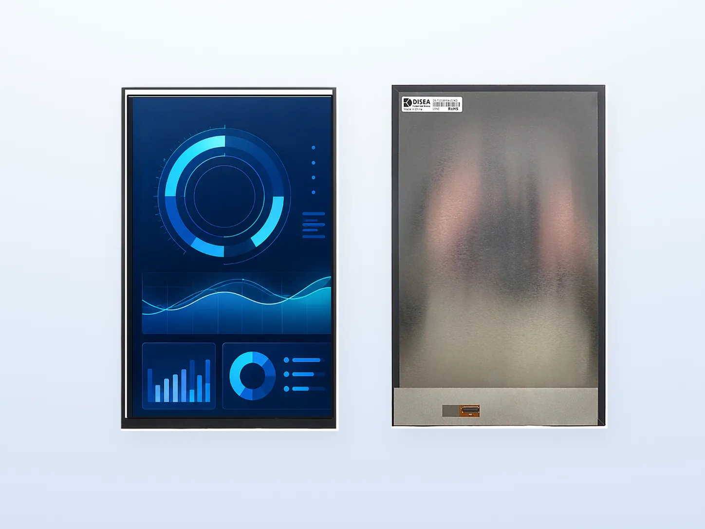
Both views represent the same native portrait module. Screen graphics are illustrative and are not included HMI software.
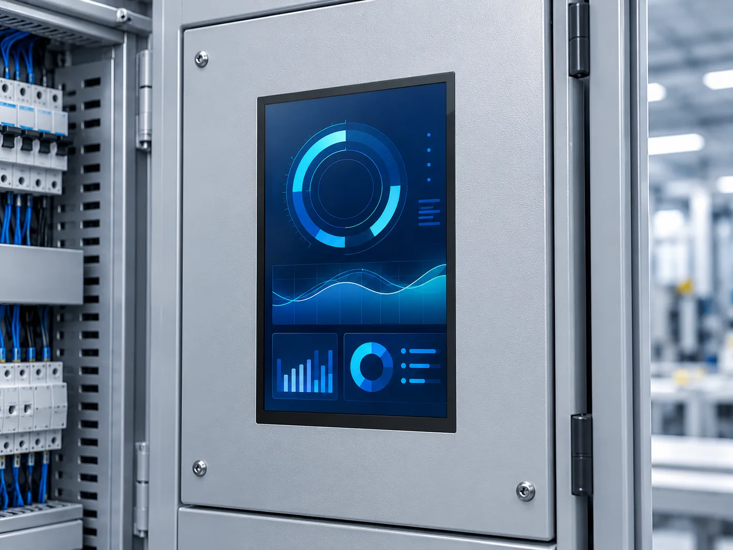
Illustrative installation only, not a documented customer deployment. The cabinet, electronics, touch function and system approvals are not included or established by this image.

A presentation setting for discussing the host, drawing and sample plan; it is not a completed test or measured result.
Identify the processor, board revision, operating system and available MIPI display output. Request the exact timing, supported operating mode, initialization sequence and power/reset requirements for this panel revision. A driver-IC name is not proof of an available host driver.
Compare the current panel pin table with the host mapping, mating connector, contact orientation, power rails and FPC route. The catalog specifies 4 lanes and 31 pins; it does not authorize a generic 31-pin cable or an adapter used with another module.
Review the 143.00×228.67×2.50 mm nominal outline with the actual mounting and rear clearance. Include connector and local protrusions from the controlled drawing. Define startup, display quality, thermal and mechanical checks for the actual host and enclosure.
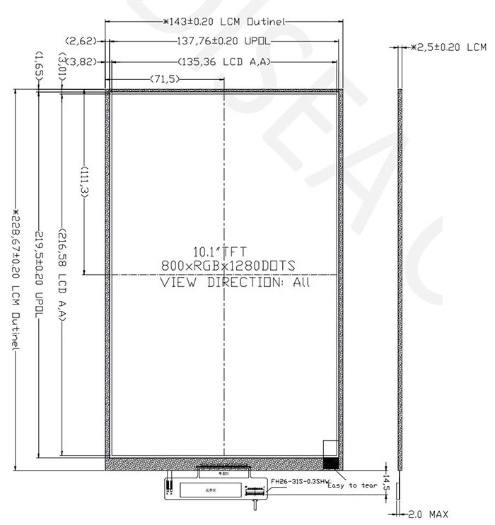
Use the original drawing at full size when reviewing the panel opening and bottom connection area.
The supplied drawing and catalog agree on the nominal 143.00×228.67×2.50 mm outline and 135.36×216.58 mm active area. The nominal module depth alone is not a complete installed-clearance envelope; check local features, connector mating, tolerances and cable clearance.
The standard module list identifies this exact model, its portrait resolution, 300 cd/m² luminance and 4-lane 31-pin MIPI connection.
View the catalog reference (page 4) · Download full catalog ↓
Summary reference only. An approved model-specific PDF is not published here. Request the current controlled datasheet, mechanical drawing, 31-pin mapping, timing and initialization information.
Include the processor/board, OS and driver arrangement, available MIPI lanes, target frame rate, proposed connection, panel opening, viewing conditions and sample schedule. Identify unresolved items instead of assuming support.
The inquiry form has no attachment field. Email authorized drawings or screenshots to mkt@diseaelec.com, or use WhatsApp with the same project reference.
Pricing, availability, document revision and sample arrangements are confirmed for the actual configuration during review.
No. DS-T101BYEA-01ND is listed with native 800×1280 portrait resolution and 4-lane 31-pin MIPI. The published landscape LVDS modules have different connections and outlines. Software rotation does not make them electrical or mechanical replacements.
No direct HDMI or USB input is specified for this bare module. A host or separately engineered bridge must support the exact panel interface, mapping, initialization, timing and power requirements. Matching pin count or a MIPI label does not establish compatibility.
No. The catalog row states no TP. The screen graphics and application scene are illustrations, not evidence of an integrated touch panel, cover assembly or supplied software. Request a separate review if touch is required.
Confirm the controlled document revision, full pin table, host/OS support, lane configuration, timing, initialization and power/reset order. The public row does not specify frame rate, lane rate or a validated host board. Keep the exact board, software and sample revision with the acceptance record.
Keep the portrait MIPI module separate from landscape LVDS and bonded-PCAP assemblies.
Compare exact modules →Verify lane planning, operating mode, software and document ownership before the FPC is frozen.
Read the MIPI review guide →Separate RGB, LVDS and MIPI panel links from host-side HDMI and controller-board decisions.
Compare interface paths →Send the portrait UI format, host platform, connection and enclosure constraints.