Short answer
Choose a factory-automation TFT LCD by the operator task, display host, touch conditions and installation environment. Keep three interfaces separate: the LCD's video link, the touch-controller connection and the machine or PLC communication handled by the host. A panel with the right resolution is not a complete industrial HMI and is not automatically compatible with a machine-control network.
Develop the display shortlist after defining the enclosure opening, viewing distance, gloves, contamination and internal temperature. Validate the chosen assembly while representative machine functions and electrical loads are active. This guide focuses on display integration and approval; it does not assign machine safety functions or certify an automation system.
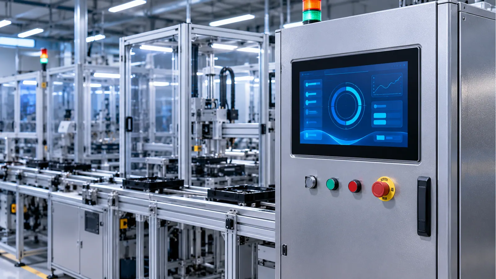
Separate the LCD module, HMI host and machine controller
A TFT LCD module presents pixels supplied by its display host. A touch controller reports input through its own connection. The HMI processor and software decide what appears on screen and how information is exchanged with the automation equipment. Treating those boundaries as one “screen interface” can hide compatibility problems until commissioning.
For example, an Ethernet connection on an HMI computer does not tell you whether a bare LCD needs RGB, LVDS or MIPI DSI. Likewise, a supported machine protocol does not establish the host's ability to drive a particular panel timing or read a particular touch controller. Document all three paths before requesting a replacement or new display sample.
Assign ownership for the host driver, user-interface software, machine communication and panel configuration. If a supplier provides a complete HMI rather than a bare display assembly, define that scope explicitly. Procurement should compare equivalent supply boundaries, not the price of a bare panel with the price of an integrated controller and enclosure.
Define the operator's information and interaction needs
List the frequent tasks: reading machine state, acknowledging information, selecting a recipe, entering values or diagnosing a fault. Identify which tasks happen from a distance and which happen close to the panel. Use actual screen content, including translated text and the longest plausible values, rather than a generic animated dashboard.
Choose the screen size and resolution around physical readability and usable control size. More pixels can support sharper graphics or additional information, but do not create a larger physical front panel. Prototype the busiest interface at the intended installation height and angle. Include the actual gloves where they are part of normal operation, and record task errors rather than relying on subjective impressions alone.
Define how the screen communicates stale data, communication loss and startup state. A frozen value that still looks current can be more confusing than a clearly unavailable value. Coordinate the user-visible behavior with the machine-control team. Safety-related decisions and protective functions remain within the OEM's product architecture and assessment, not within a generic LCD-selection article.

Match each factory condition to a verification boundary
The environment changes which evidence is needed. Avoid turning an application label such as “factory automation” into a universal module rating.
| Installation condition | Selection question | What to validate |
|---|---|---|
| Indoor control cabinet | Can the host drive the native panel and touch interfaces? | Video, input, startup and software recovery |
| Bright production area | Are task text and alarms readable through the final cover? | Reflections, viewing angles and dimmed operation |
| Gloved operation | Does the specified touch assembly support the actual gloves? | Edge targets, repeated gestures and unintended input |
| Dust, residue or cleaning | What front-panel construction and service procedure are intended? | Complete enclosure and approved cleaning process |
| Nearby motors and switching loads | Does system operation disturb display or touch behavior? | Production-like wiring, grounding and load states |
| Hot or cold installation | What temperatures and startup states apply to each component? | Powered assembly and the agreed environmental program |
Use the factory-automation application page to identify the commercial selection path. This guide supplies the integration questions needed to evaluate a shortlist; it is not a claim that every listed display is suitable for every row of the matrix.
Close display-link compatibility before designing the harness
Record the host output, selected panel interface, native timing and color mapping. Include supply rails, connector orientation, reset behavior and backlight control. If the host and panel require a bridge, treat that bridge as another documented component with power, timing and software requirements. A connector adapter alone does not resolve incompatible video formats.
For an existing machine, inspect the controlled wiring and current panel documentation. Similar diagonals and resolutions do not prove matching pinouts, power sequencing or mounting details. Do not discover compatibility by connecting an unknown module to a live machine. Establish a documented bench configuration before progressing to controlled system testing.
Use the TFT LCD interface guide for the decision framework, then the selected model's documents for the actual connection. Keep the display cable and touch link identified separately on the harness drawing. Label signal names, channel assignment and connector orientation so the drawing can be reviewed without guessing from a photograph.
Consider installation and servicing while routing cables. Define strain relief, connector access and clearance around door hinges or moving parts. The intended harness length and route should be tested in the system; a successful short bench cable is not evidence for an untested cabinet installation. Any later harness substitution should go through the agreed change review.
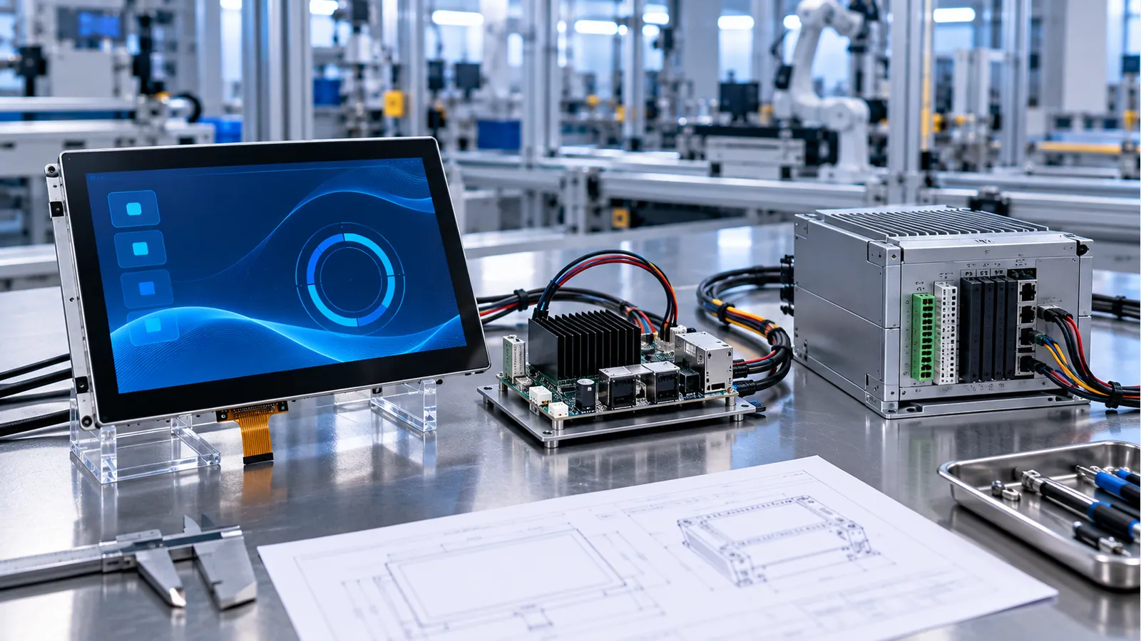
Test touch with the real electrical environment
List glove materials and operating conditions rather than specifying only “glove support.” Add contamination and cleaning scenarios that are actually expected. Define which gestures are necessary and what behavior is acceptable when the surface is wet or dirty. Intentional input, missed input and false input should be recorded separately.
Texas Instruments' industrial capacitive-touch article discusses noise from motors, relays and switches as a sensing challenge. Its capacitive-button examples are not touchscreen specifications. The practical implication here is to include relevant electrical load states in the final assembly's test plan, using the selected controller's documentation.
Compare the quiet-bench result with the installed result while representative loads switch. Record video disturbances, touch coordinates, unintended events, communication interruptions and recovery. Change one variable at a time during diagnosis; replacing the sensor, power supply and cable together can obscure the cause and leave no repeatable production fix.
Review the cover, sensor, controller configuration and enclosure grounding as one touch system. The industrial PCAP design guide helps define that boundary. Do not promise wet or glove behavior solely from the word PCAP, and do not copy thickness limits from a capacitive-button demonstration into a multi-touch requirement.
Check temperature and optics at the installation point
Distinguish room temperature from temperature inside a closed, powered cabinet. Identify nearby processors, power supplies, backlight drivers and other heat sources. Use the selected components' stated measurement conditions and limits, then define where the system test will measure temperature. A wide-temperature panel does not extend the rating of every other part in the assembly.
Review cold startup if the machine must operate immediately after an unpowered cold period. Storage survival, powered operation and startup response are different questions. The wide-temperature TFT selection guide explains how to organize those requirements without treating a storage range as an operating guarantee.
Check visibility from actual operator positions. A panel installed high on a cabinet, low beside a workstation or behind a reflective cover has different viewing geometry. Evaluate text, alarm symbols and dark-state reflections through the finished optical stack. Do not infer a usable viewing cone solely from a photograph or a generic panel-type label.
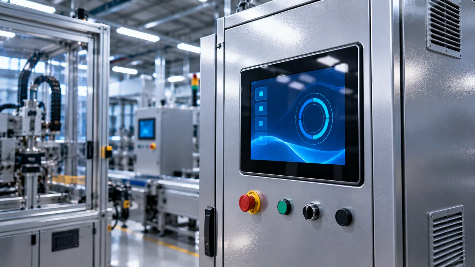
Plan maintenance and configuration control early
Determine what the maintenance team replaces: LCD, touch assembly, controller, harness or complete front panel. Identify which seals or adjustments are disturbed by that process. A replacement part needs documented compatibility and an approval record; using the same diagonal and pixel count is not sufficient.
Keep a configuration record linking the model, drawing, harness, controller firmware and host software. If touch tuning is supplied as a configuration file, establish who owns it and how a repaired unit receives the approved version. Capture the commissioning settings that matter, rather than allowing each technician to recreate them from memory.
Ask procurement to distinguish documented availability information from assumptions about unlimited supply or interchangeability. Define what happens when a component or process changes: notification, document review, sample validation and approval ownership. This reduces the risk of receiving a visually similar assembly that has different electrical or optical behavior.
A factory-HMI display selection flow
- Identify the operator tasks, physical viewing geometry and enclosure boundary. If screen content is still undecided, prototype it before freezing resolution.
- Document the video, touch and machine-communication paths separately. Resolve unsupported host interfaces before committing to a panel or harness.
- Shortlist documented assemblies against mechanical, optical and temperature constraints. List unresolved facts instead of filling them with assumptions.
- Review gloves, contamination, wiring and electrical load states with the touch and machine teams. Define reproducible acceptance tests.
- Validate a production-like unit, then freeze the approved assembly and service configuration with clear retest triggers.
A proposal should show both the chosen configuration and the evidence still required. “Industrial grade” is not a substitute for that record. Request the sample-validation checklist when organizing approval across engineering, quality and procurement.
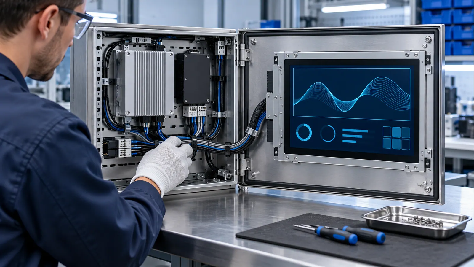
Commissioning and release checklist
- Identify the LCD, touch, cover, harness, host and software revisions of the tested unit.
- Verify native image mapping with edge markers, fine lines, gradients and representative application screens.
- Exercise the interface while machine communications and representative background workloads are active.
- Test intentional touch, missed input and unintended activation with the specified gloves and contamination.
- Check display and touch behavior during the agreed motor, relay and switching-load states.
- Verify the user-visible response to startup, interrupted communication, suspend and recovery.
- Measure the agreed thermal points in the closed enclosure under demanding operating conditions.
- Inspect cable retention, connector access and service replacement using the actual maintenance procedure.
- Record the pass/fail criteria, logs and remaining limitations before signing off the assembly.
Repeat affected tests when a change alters the verified boundary. A new cover thickness may require touch review; a new host image may require driver and recovery tests; a harness-route change may require installed electrical checks. Change control makes a successful prototype result useful for subsequent production units.
Frequently asked questions
Can a bare TFT LCD connect directly to a PLC network?
Do not assume it can. A bare panel needs its specified video link, while the HMI host handles application software and machine communications. A complete HMI product may integrate those functions, but its scope and supported protocols must be documented separately.
Is LVDS always the best interface for factory automation?
No interface is universally best. Match the host, panel timing, wiring and integration constraints. Compare current model documentation and test the intended harness. An application category does not override electrical compatibility.
Does an industrial touchscreen automatically support gloves?
No. Support depends on the sensor, cover, controller configuration and glove conditions. Specify the actual gloves and required gestures, then validate the installed assembly, including relevant electrical load states.
Can a panel be replaced solely by matching size and resolution?
No. Compare pinout, timing, supply, mounting, optical stack, touch connection and software requirements. Obtain the controlled documents and validate the replacement before release. Visual similarity is not an interchangeability record.
What makes a factory-HMI RFQ useful?
Include host details, the three interface boundaries, representative screens, enclosure drawings, viewing positions, gloves, contamination and temperatures. Add the maintenance strategy and unresolved requirements so the supplier can review the actual design problem.
Continue the HMI integration review
For a custom front panel, the cover-glass design guide helps specify the viewing window and edge support. Where the HMI has dense graphical screens, the 10.1-inch resolution comparison explains why physical text size, host resources and the exact assembly matter alongside pixel count.
Request a factory-HMI display review
Share the installation and host requirements through the project review form. A documented boundary between display hardware, HMI software and machine control helps the team propose a suitable sample and a validation plan without overstating the capability of a bare module.