Short answer
Select a 10.1-inch industrial TFT LCD by the information an operator must read, the host's native output and the complete front-panel assembly—not by resolution alone. Both 1280×800 and 1920×1200 have a 16:10 pixel ratio. The higher resolution contains 2.25 times as many pixels, but does not create a larger physical screen or automatically improve touch usability. Prototype the actual interface at its intended viewing distance before choosing.
For TFTWorks' published bonded PCAP configurations, resolution is also tied to different interfaces, luminance and temperature limits. This guide separates those documented product differences from calculated graphics requirements. Product specifications below reflect the current catalog; obtain the latest controlled datasheet and assembly drawing before design-in.
Start with the operator's task, not a pixel-count target
A machine-status screen, a recipe editor and a detailed inspection interface can all use a nominal 10.1-inch display, yet place very different demands on it. Write down the three most important tasks: identifying an alarm, entering a value and comparing several readings, for example. Capture the longest translated labels, the smallest necessary text and the number of simultaneous controls. Then create native-resolution mockups of the busiest screen, rather than comparing attractive dashboard photographs.
At the same physical display size, increasing the pixel count allows finer rendering or more content. Those are different design choices. If software keeps the same pixel-sized font, the text becomes physically smaller. If it scales the font to preserve physical size, the benefit is smoother lettering rather than extra controls. Agree which outcome the product needs. A higher-resolution panel cannot compensate for a crowded layout, ambiguous alarms or controls too small for the intended gloves.
Use a printed or on-screen physical-size reference during review. Ask operators to perform representative tasks without explaining where to tap. Record missed controls, incorrect readings and required navigation. Treat these observations as project-specific evidence; they are more useful than assuming that all industrial interfaces require the highest available resolution.
Compare the documented assemblies, not just their diagonal
The following are two separate published TFTWorks configurations. Neither is presented as a drop-in substitute for the other. Their PCAP designation and optical bonding do not establish universal glove, wet-touch or outdoor performance.
| Published item | DS-T101HIEWA-01CP | DS-T101BFHA-01CP |
|---|---|---|
| Diagonal and resolution | 10.1 inch, 1280×800 | 10.1 inch, 1920×1200 |
| LCD type | IPS | IPS |
| Catalog luminance | 850 cd/m² | 1000 cd/m² |
| Display interface | LVDS 6/8-bit, 40-pin | LVDS 2-channel, 8-bit, 45-pin |
| Touch and front stack | PCAP, ILI2511, optical bonding | PCAP, ILI2511, optical bonding |
| Published assembly outline | 260.00×170.00×6.95 mm | 260.00×170.00×6.73 mm |
| Operating temperature | −30 to +85 °C | −20 to +70 °C |
| Storage temperature | −30 to +85 °C | −30 to +80 °C |
Read the 1280×800 bonded PCAP product page and the 1920×1200 bonded PCAP product page for their individual documentation. A shared controller name does not prove identical touch firmware or identical environmental behavior.
The 1920×1200 page also distinguishes its supplied base-LCD drawing from the complete CP assembly. That distinction matters: an enclosure cannot be released against a bare-panel outline when a larger cover lens and touch assembly must fit. Compare drawing revisions, visible opening, adhesive area, stack depth and cable exits, even when the nominal assembly width and height match.
Calculate graphics storage before changing the host
The active pixel counts are 1280×800 = 1,024,000 and 1920×1200 = 2,304,000. For a tightly packed single framebuffer, storage equals width × height × stored bytes per pixel. The following calculations use decimal megabytes, where 1 MB equals 1,000,000 bytes. They exclude stride padding, extra buffers, textures and operating-system allocations.
| Assumed stored format | 1280×800, one buffer | 1920×1200, one buffer |
|---|---|---|
| RGB565, 2 bytes/pixel | 2.048 MB | 4.608 MB |
| Packed RGB888, 3 bytes/pixel | 3.072 MB | 6.912 MB |
| ARGB8888, 4 bytes/pixel | 4.096 MB | 9.216 MB |
Double buffering doubles these particular allocations; triple buffering triples them. A graphics stack may store nominal 24-bit color in a 32-bit field, so confirm the actual memory format rather than inferring it from the LCD's color specification. NXP's graphics and LCD introduction explains the framebuffer model and distinguishes memory organization from panel data mapping.
As a calculation example—not a claimed refresh specification—60 complete active frames per second would contain 61.44 million or 138.24 million active pixels per second respectively. This is not the required LVDS serial rate or the complete timing pixel clock. Obtain the panel's total horizontal and vertical timing, blanking and mapping from its datasheet. Rendering, compositing and scan-out can impose different memory transactions; a pixel-count ratio is not a measured CPU-load ratio.
Close the interface and software questions together
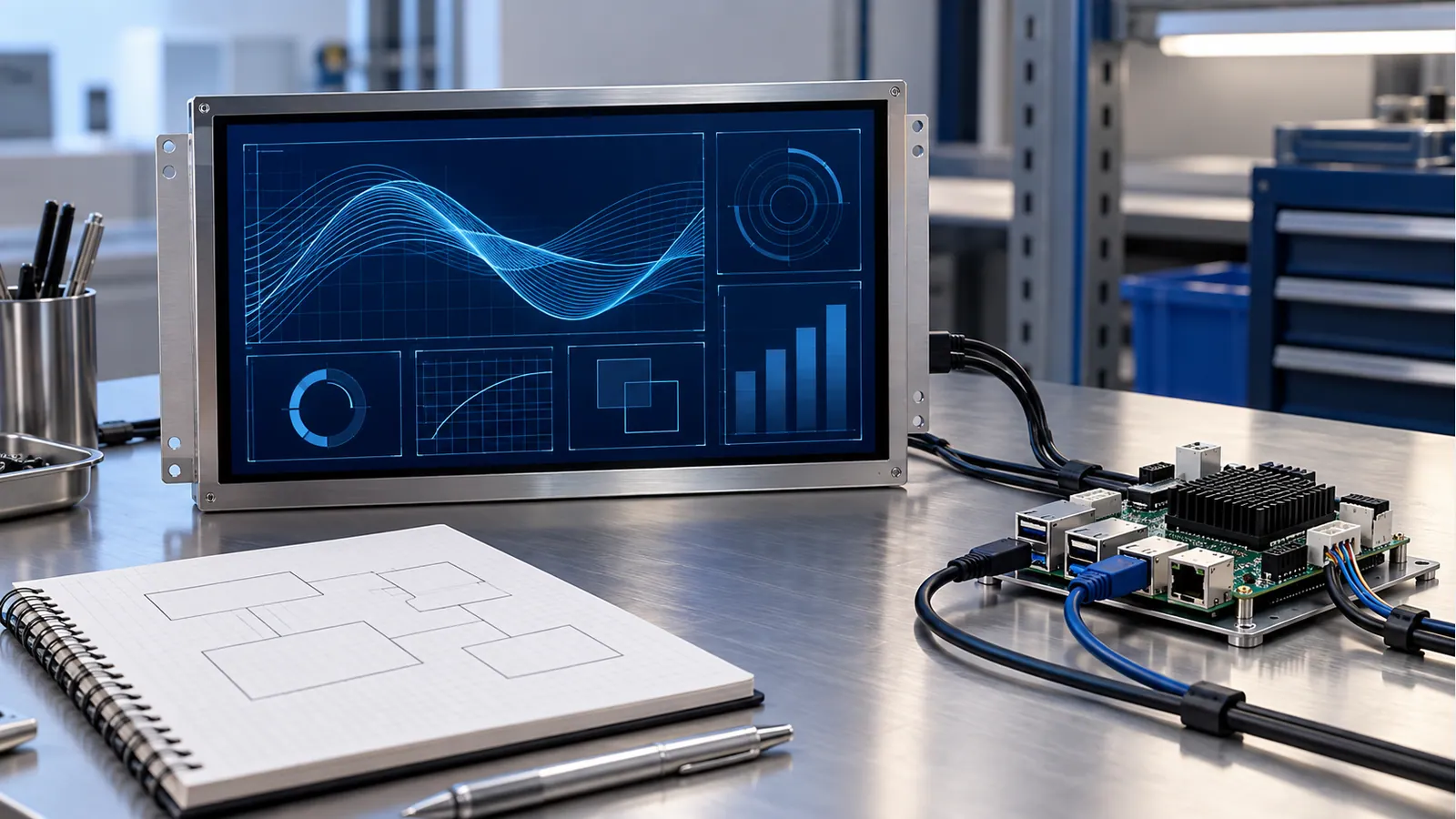
The host must support the exact display link, not simply advertise a maximum resolution larger than the panel. Check whether its output is LVDS, RGB, MIPI DSI, HDMI or another format, and whether a bridge is involved. For the catalog comparison above, the 40-pin LVDS configuration and the dual-channel 45-pin configuration require separate pinout and mapping reviews. A passive cable does not turn an incompatible interface into a compatible one.
Create a connection worksheet with supply rails, power sequencing, connector orientation, channel assignment, color mapping, reset behavior and backlight control. Use current documents for the selected assembly. Keep the display-data interface separate from the touch-controller connection; successful video output does not prove that touch input, interrupt handling or recovery after suspend will work.
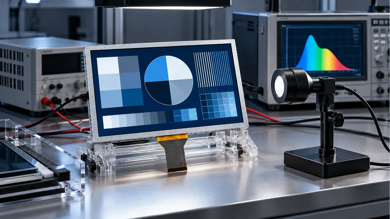
Bring up native timing with a simple test pattern before loading the production interface. Check single-pixel lines, gradients, full-screen colors and edge markers for mapping or scaling errors. Then run the actual software with logging, communication and background workloads active. The TFT LCD interface guide provides the wider compatibility workflow; it is not a substitute for the selected model's electrical documentation.
Preserve physical readability through the front stack
Compare the display with the intended cover, bonding, surface finish and enclosure opening installed. A bare sample viewed straight-on at a bench is not the finished HMI. Test overhead reflections, off-axis positions and dimmed operation. If the operator uses polarized eyewear, include that exact condition in the review rather than making a universal promise about panel visibility.
Brightness is another independent variable. The two catalog luminance values above should not be interpreted as a controlled resolution experiment because the complete configurations differ. Evaluate the chosen assembly's optical output and thermal behavior under the actual drive conditions. A requirement for cold operation may favor a different model from one favored by the densest graphics layout.
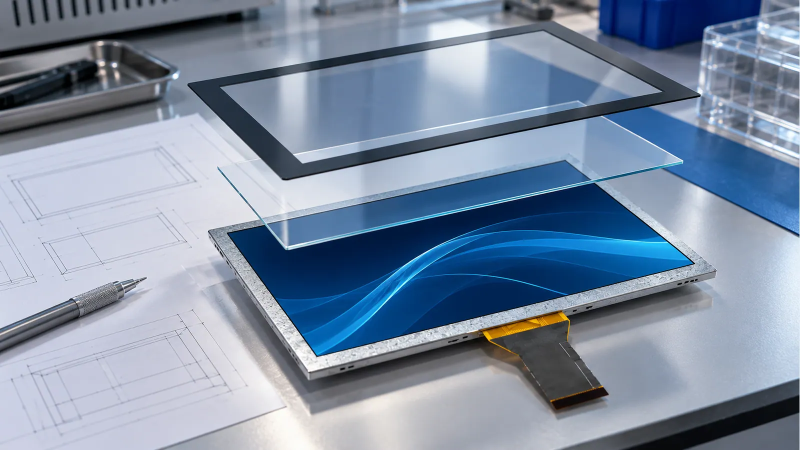
Keep cover-lens changes under configuration control. Changing thickness, printed border, bonding material or enclosure support can affect the integration even if the LCD resolution remains unchanged. For touch-stack planning, use the industrial PCAP design guide alongside the assembly supplier's instructions.
A practical 10.1-inch selection flow
- Define the viewing distance, installation orientation, glove conditions and busiest translated screen. If physical text or control size is unclear, resolve that before requesting samples.
- Prototype 1280×800 first as a candidate, not an automatic default. If necessary information cannot fit without compromising usability, evaluate a scaled 1920×1200 layout.
- Confirm native host timing, channel mapping and stored pixel format. If the interface is unsupported, compare a documented bridge or a different host before freezing the panel.
- Compare complete configurations for temperature, luminance, touch stack, outline and cable routing. Reject candidates that miss a mandatory environmental or mechanical requirement.
- Validate the shortlisted assembly with production software in the intended enclosure. Release the configuration only after the acceptance criteria are met.
Browse the industrial TFT size catalog when the available front-panel space or the operator's task suggests reconsidering the diagonal. Choosing a larger screen can be a more direct usability solution than making text smaller on the same screen.
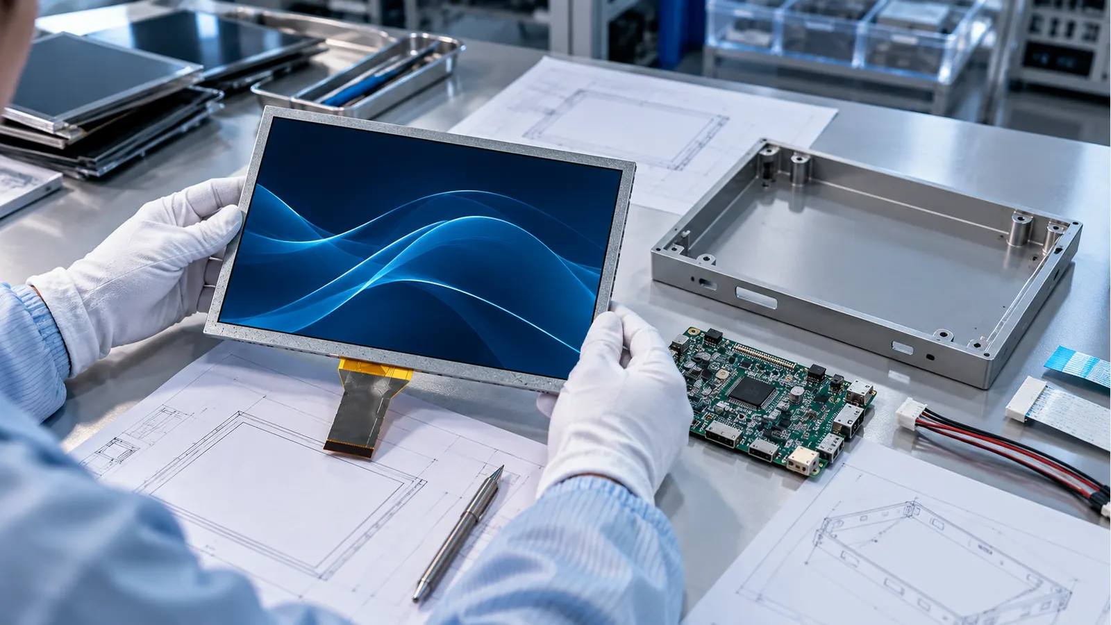
Sample validation checklist
- Record model, drawing revision, touch configuration and software build. Identify any difference between the sample and the intended production assembly.
- Confirm startup, repeated power cycling, suspend/resume and recovery after an interrupted connection under the agreed test procedure.
- Exercise the busiest interface while communications and background workloads run. Record response delays rather than reporting only average frame rate.
- Check text, thin traces, alarms and translated labels at the intended distance, angle and ambient-light conditions.
- Test touch accuracy near edges and corners with the specified cover, gloves and contamination conditions.
- Check cable strain, connector access, stack clearance and service removal in the assembled enclosure.
- Measure temperatures at agreed locations while the backlight and host operate at the project's demanding settings. Use component limits from controlled documentation.
- Freeze approved hardware, firmware and optical-stack revisions, with explicit triggers for retesting after changes.
Define pass/fail criteria before testing. “Looks clear” is too vague to guide a supplier or compare two samples. State the task the operator must complete, the allowed response behavior and the environment in which the result must hold. Keep photographs and test logs with the released assembly revision.
Frequently asked questions
Is 1920×1200 always better for a 10.1-inch HMI?
No. It offers more pixels, but usefulness depends on physical text size, task density, software scaling and host capability. A well-designed 1280×800 screen may be easier to operate than an overcrowded higher-resolution interface. Use task-based mockups to decide.
Can these two 10.1-inch PCAP assemblies use the same cable?
Do not assume so. Their published interfaces are LVDS 6/8-bit 40-pin and dual-channel 8-bit LVDS 45-pin. Confirm connector, power, channel mapping and timing for each configuration; nominal size is not electrical compatibility.
Does the higher resolution require exactly 2.25 times more processing power?
No. The active pixel count and the tightly packed framebuffer storage at the same stored format increase by 2.25 times. Actual processing load depends on redraws, compositing, acceleration and memory traffic. Measure the production workload on the intended host.
Does bonded PCAP guarantee operation with water or gloves?
No. Those are assembly- and configuration-specific requirements. Validate the selected cover, controller settings, gloves, water condition and grounding in the final enclosure rather than extending a generic PCAP label into a performance guarantee.
What should accompany a sample request?
Send the native interface, proposed resolution, representative screens, viewing distance, enclosure drawing, temperature requirement and touch conditions. Include the project schedule and quantity so that the engineering review can address both integration and supply planning.
Continue the selection
If the same resolution decision concerns an instrument rather than an HMI, review how trace layout and acquisition are kept separate in the test-and-measurement TFT guide. For a custom front panel, the cover-glass design guide helps define the drawing and validation inputs.
Request a configuration review
Use the project review form to share the host platform, enclosure constraints and actual user-interface requirements. Specify which facts are mandatory and which are still open. The goal is an approved 10.1-inch assembly and a repeatable validation plan—not simply a panel with the largest pixel count.