Short answer
Select an EV-charging-station TFT LCD as part of the charger's front-panel, thermal and user-interface design. Begin with installation exposure, driver viewing positions, required information and touch conditions. Then shortlist documented modules for the host interface and environmental limits. Validate readability, touch and temperature together in the actual enclosure.
A high panel-luminance value alone does not prove sunlight readability, and a PCAP label alone does not establish wet or gloved operation. The finished charger also includes a cover, bonding or air gaps, seals, backlight driver, power electronics and software. This engineering guide addresses their display-related interfaces; it does not certify a charging station or claim that an illustrated installation is a customer deployment.

Describe where and how the charger will be used
Separate sheltered installations from locations exposed to direct sun and rain. Note the screen orientation, nearby reflective surfaces and whether the enclosure is shaded throughout the day or only at certain times. Local ambient temperature is one input, but it is not automatically the temperature of the LCD, touch controller or backlight inside a powered cabinet.
Describe the user journey before picking a diagonal. The screen may need to show connection instructions, session progress, pricing information supplied by the operator, errors and assistance. Identify which items must be readable from a standing position and which require close interaction. Include the longest supported translation and the planned accessibility review; a dense desktop dashboard is not necessarily a good outdoor charging interface.
Decide which actions require touch and which may use separate controls or an alternative interface. Avoid assigning essential behavior to a visual icon whose meaning depends on an unexplained color. Test the sequence with representative users. The purpose is to define the actual information and interaction problem, not to assume that a larger or brighter panel resolves every usability issue.
Build a display requirements matrix
Use the following matrix to prepare a supplier discussion. Fill it with project requirements and acceptance criteria; it is not a declaration that a particular module meets them.
| Design question | Information to supply | Validation boundary |
|---|---|---|
| Sun and reflections | Screen orientation, cover treatment and expected exposure | Complete front stack at representative viewing positions |
| Touch interaction | Gloves, rain, droplets, wiping and required gestures | Actual sensor, controller configuration and enclosure grounding |
| Temperature | Ambient range, internal heat sources and operating states | Powered assembly, cold startup and hot operating conditions |
| Host compatibility | Native video output, software and timing needs | Selected display link, touch connection and recovery behavior |
| Mechanics | Front opening, attachment, cable path and service access | Controlled drawings and assembled enclosure |
| Maintenance | Cleaning procedure, replaceable unit and revision policy | Appearance and function after the agreed service procedure |
Keep mandatory limits separate from preferences. A front-panel width that cannot change is a constraint; a preferred dashboard layout may be adjustable. When a supplier proposes a different assembly, ask which requirements it satisfies, which remain unverified and which require a host or enclosure change.
Evaluate readability with the complete optical stack
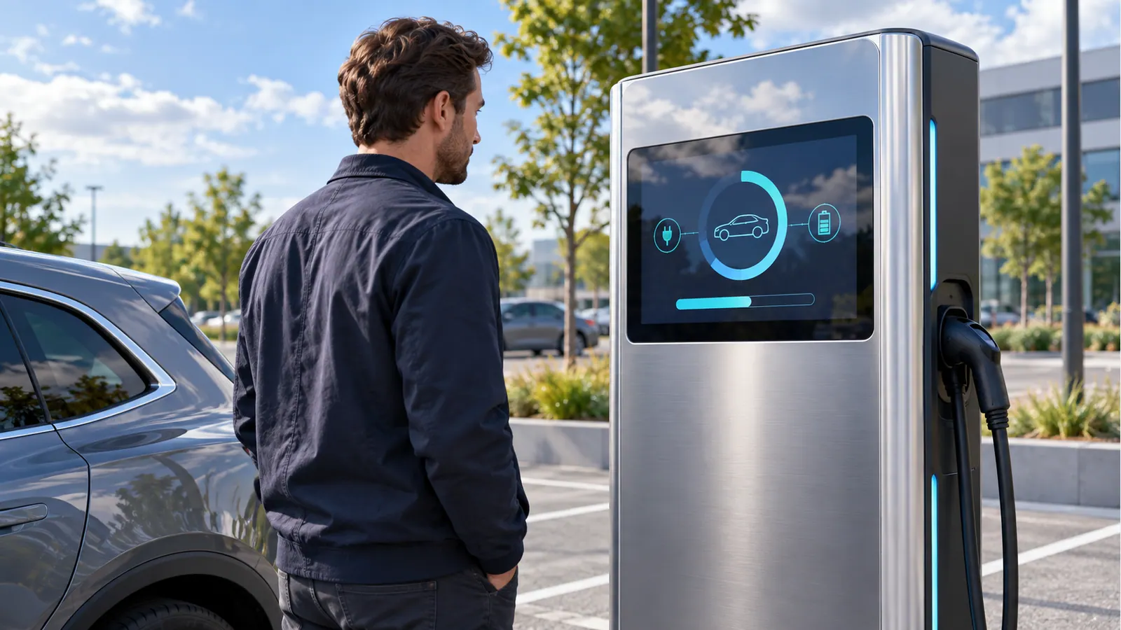
Inspect more than a white-screen brightness measurement. Review the actual interface through the chosen cover and touch stack under the intended illumination. Dark backgrounds, status text and small icons may behave differently from a full-white image. Look for reflected sky, nearby vehicles, signs or canopy lighting across the positions from which drivers interact with the charger.
Separate panel luminance from reflected light and front-stack losses. The sunlight-readable TFT guide explains why brightness and reflections must be evaluated together. Use the panel's current specification as an input, not as a guarantee that the finished charger is readable in every outdoor condition.
If comparing two optical constructions, control the screen content, drive conditions, camera exposure and viewing geometry. Otherwise a photograph may show a different exposure setting rather than a real readability difference. Record whether the comparison uses the same LCD, different cover treatments or entirely different assemblies. Do not label an uncontrolled concept image as an optical test result.
Discuss night operation as well as daylight. Establish a usable dimming range and behavior if an ambient-light sensor is present, absent or obstructed. Check transitions rather than only minimum and maximum settings. A dimming policy should preserve legibility without assuming that continuous maximum drive is required throughout every session.
Define wet and gloved touch as testable behaviors
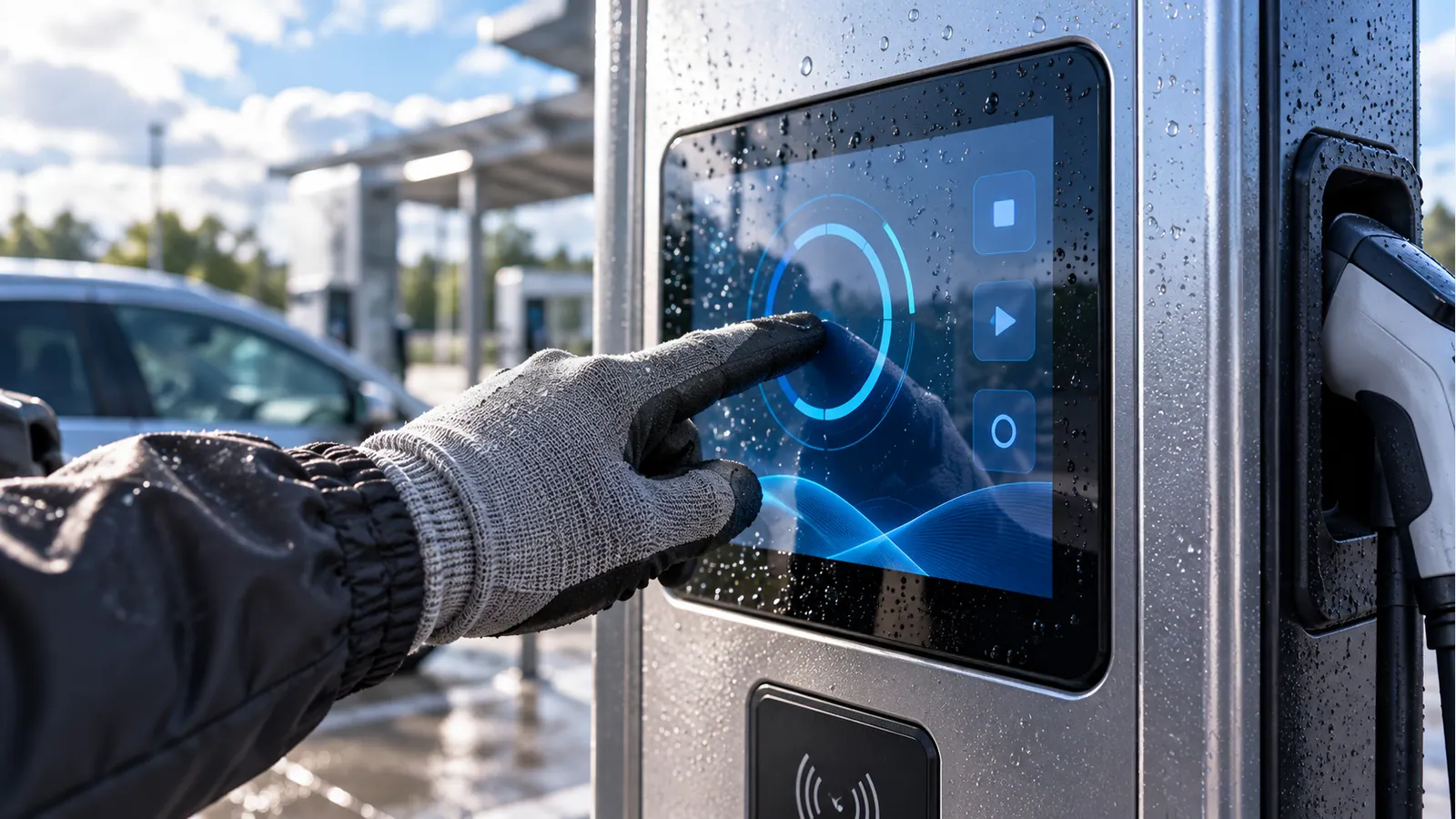
“Outdoor PCAP” is too broad for a release requirement. Describe dry gloves, wet gloves, isolated droplets, a water film and wiping as separate conditions where relevant. Define what the interface should do when intentional touches become difficult to distinguish from contamination. A documented requirement might prioritize rejection of unintended input over acceptance of every possible wet gesture.
Microchip's maXTouch overview describes controller families designed for challenging moisture, noise and front-panel conditions. This demonstrates the need to select and configure a suitable touch system; it is not evidence that every PCAP module, or a particular TFTWorks assembly, has those capabilities.
Request the touch-controller identity, interface, configuration ownership and firmware-change process for the proposed assembly. Include the actual cover lens, enclosure frame and grounding in tests. Repeat checks while the charger operates in its demanding electrical states, not just while the display is powered independently at a quiet bench. Do not transfer a good bare-sensor result to an untested finished cabinet.
Plan for internal heat and solar exposure together
Create a thermal map of the cabinet. Identify the LCD, backlight, driver, processor, power supplies and nearby heat-producing assemblies, plus the intended paths by which heat leaves them. Include installation orientation, ventilation restrictions and any separation between the user-interface compartment and the rest of the charger.
Define measurement locations and operating states before testing. A panel rating should be interpreted using the supplier's stated conditions, not compared casually with a single air-temperature reading elsewhere in the enclosure. The high-brightness thermal trade-offs guide provides a display-focused planning framework. Current component documents remain the authority for individual limits.
Test combinations that represent the demanding project conditions: extended operation, the selected backlight drive, enclosure closure and defined solar exposure where applicable. Record temperature versus time so that a short demonstration is not mistaken for a stable operating condition. If a control policy reduces brightness or changes operation during heat, verify that users still receive the required information.
Cold startup is a separate review. Establish when the charger must become readable and responsive, whether preheating is part of the design and what the interface does during initialization. Storage limits do not by themselves establish powered startup behavior. Do not advertise a complete charger's temperature capability from a display's storage range.
Confirm electrical and mechanical integration before tooling
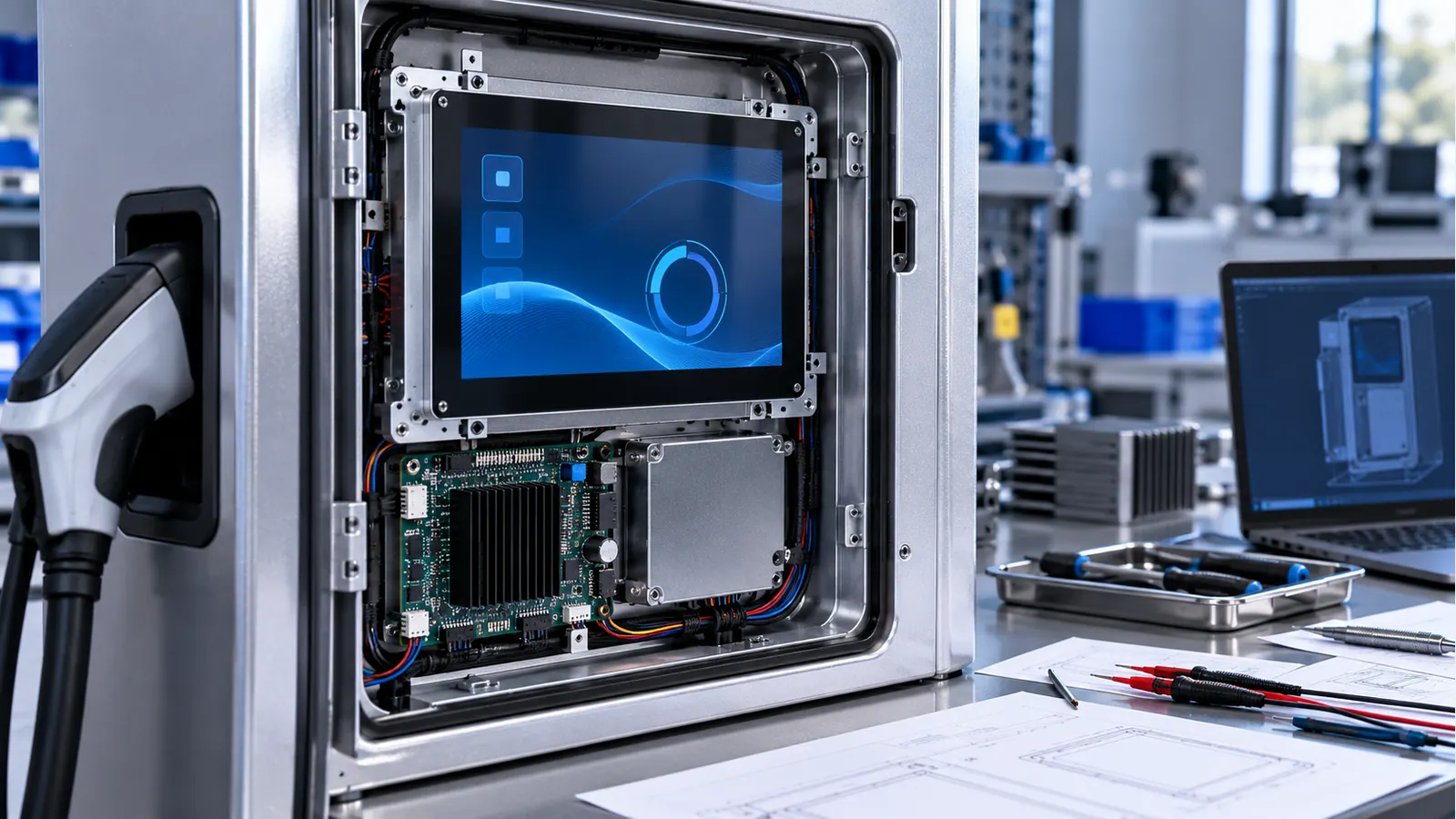
Use the host's native video output to narrow the display shortlist. If a bridge board is needed, document its power, timing, software and cable interfaces as part of the system. Keep the touch data link separate from the LCD link and define startup, disconnect and recovery behavior for each. The connector fit alone is not proof of compatibility.
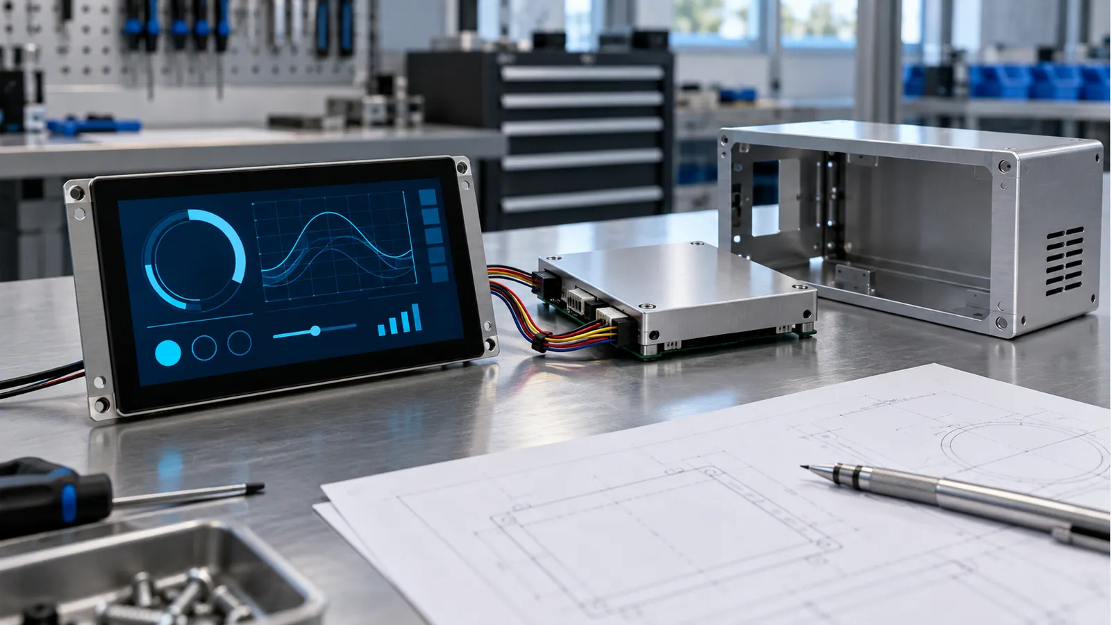
Review cable exits, bend clearance, strain relief and connector accessibility against the enclosure drawing. An integrated cover lens can extend beyond the LCD's metal outline, so use the complete assembly drawing for the front-panel opening and attachment. Identify how seals and mounting pressure are supported without creating an undocumented load on the display stack.
Plan service before locking the construction. Decide whether technicians replace a bare panel, a bonded display stack or a complete front-panel module. Consider connector reach and whether replacement disturbs seals or requires touch reconfiguration. Record the intended repair workflow rather than assuming that optical bonding is either always serviceable or always disposable.
The EV-charger application page provides the commercial selection path. Use this guide to build the engineering brief that accompanies a shortlist; application relevance is not a declaration of a documented customer installation.
An EV-charger display selection flow
- Define exposure and the driver tasks. If viewing positions or wet-input behavior are unresolved, establish them before specifying a panel-luminance target.
- Select a screen size and resolution using physical-size interface mockups. Preserve required text and control size through translation.
- Match the native video and touch interfaces, complete drawing and environmental requirements to documented candidate assemblies.
- Review the optical stack, sealing boundary and thermal design with the enclosure team. Remove candidates that cannot meet a mandatory interface or geometry constraint.
- Test the production-like front panel and software under the agreed combined conditions. Freeze the assembly only when the acceptance criteria are met.
Use the high-brightness catalog to identify candidates, then compare their individual data rather than treating the category name as a qualification result. Some projects may need changes to the cover or enclosure more than a change to the LCD itself.
Validation checklist for the finished front panel
- Record the LCD, touch, cover, bonding, firmware and enclosure revisions of the tested assembly.
- Evaluate representative screens in daylight, shadow and night conditions at the intended viewing positions.
- Test specified gloves, moisture and wiping conditions, recording both missed input and unintended activation.
- Check touch behavior while the charger and nearby electrical equipment operate in the agreed test states.
- Verify startup, repeated power cycling, communication interruptions and the user-visible recovery behavior.
- Measure agreed thermal points over the defined operating duration with the complete enclosure closed.
- Inspect mechanical retention, cable strain, opening alignment and service access.
- Apply the approved cleaning procedure and repeat relevant appearance and functional checks.
- Retest the affected areas after changes to the cover, controller configuration, backlight policy or mounting construction.
Document the limits of each test. A readability review, touch exercise or thermal test does not automatically establish electrical safety, ingress protection, payment compliance or whole-charger certification. Those requirements belong to the OEM's applicable product program and need their own evidence.

Frequently asked questions
What brightness does an EV-charger display need?
There is no universal value for every installation. Define exposure, reflections, front-stack construction, interface contrast and viewing positions, then test shortlisted assemblies. Panel luminance is one selection input, not a finished-system readability guarantee.
Does PCAP work reliably in rain?
That depends on the sensor, controller, configuration, cover, grounding and defined water condition. Specify the required behavior and validate the actual front panel. Avoid extending a generic PCAP description into a promise of unrestricted wet operation.
Can the LCD's temperature range be used as the charger's range?
No. The complete charger includes other components, internal heat and installation effects. Interpret each component's limits correctly and validate the assembled product. Powered cold startup should also be reviewed separately from storage.
Is optical bonding mandatory?
Not for every project. Compare the intended optical result, environmental conditions, assembly process and repair strategy. Validate the selected stack instead of assuming that bonding alone establishes outdoor suitability or sealing performance.
What should be sent for an engineering review?
Provide host details, enclosure drawings, sunlight exposure, temperature conditions, representative screens, gloves and water scenarios. Add the intended maintenance method, quantity and schedule. Mark unresolved requirements so that a quotation does not silently assume them.
Continue the outdoor front-panel review
The cover-glass design guide covers lens drawings, printed borders, edge support and stack validation. Those choices must still be checked against the charger's own exposure and enclosure design.
Request an EV-charger display review
Submit the front-panel requirements through the project review form. A clear exposure, interface and validation brief helps the team assess a documented display assembly without making unsupported promises about the finished charger.